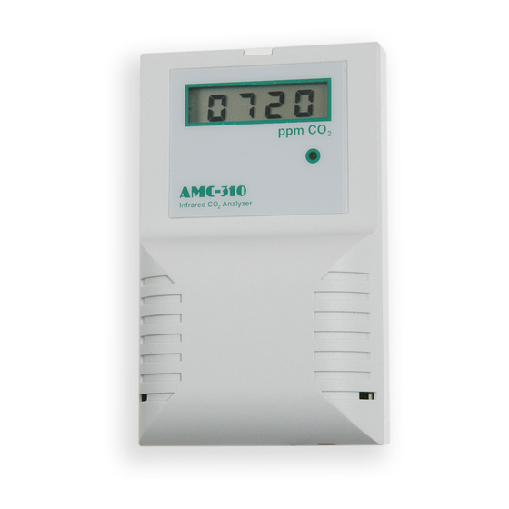
Armstrong Monitoring Corporation AMC-310 Manuel d'instructions - Page 15
Parcourez en ligne ou téléchargez le pdf Manuel d'instructions pour {nom_de_la_catégorie} Armstrong Monitoring Corporation AMC-310. Armstrong Monitoring Corporation AMC-310 18 pages. Airsense infrared co2 analyzer

6 Calibration
This section describes the calibration verification procedure and calibration adjustment
procedures.
6.1 Verification Procedure
A quick but approximate calibration verification can be done by supplying the unit with outside
air and letting the reading stabilize. CO
and 450 ppm. A more accurate calibration check requires the use of calibration gas of known
concentration; a 1/8" I.D. flexible tube, regulator and calibration gas cylinder are needed. To
verify the Model 310's calibration, proceed as follows:
1. Remove the front cover of the unit (see procedure on page 7).
2. If there is no display on the unit being calibrated, connect a current or volt meter to the
analog output terminals. Check the setting of the analog output selector (see Figure 2
on page 8) to determine whether the unit is set for voltage or current output.
3. Note whether the shorting block at jumper JP5 is covering both pins or only a single pin,
then borrow the shorting block and slide it over both pins of jumper JP2 (see Figure 2 on
page 8).
4. Remove the dust cover from the calibration nipple, attach a flexible tube and establish a
flow of between 50 and 100 cc/min (0.1 to 0.2 SCFM) of calibration gas through the
sensor. Allow approximately two minutes for the reading to stabilize.
5. If the reading differs by more than ± 75 ppm from the known concentration of the
calibration gas, use the 'UP' and 'DOWN' buttons (see Figure 2 on page 8) to adjust the
reading.
6. When the reading agrees with the concentration of the calibration gas, remove the
shorting block on jumper JP2, and replace in its original position at jumper JP5.
7. Turn off the calibration gas flow, disconnect the gas tubing from the calibration nipple
and replace its dust cover. Remove the meter leads from the terminal strip and replace
the front cover (see procedure on page 10).
6.2 High CO
Limit
2
An adjustable high CO
changes from steady to blinking when the indicated concentration is above the high CO
value. An optional contact closure is available which opens or closes when the high limit is
exceeded.
6.2.1 Adjusting the High CO
The setpoint value is adjusted by closing jumper JP3 (see Figure 2 on page 8). If the display is
present when JP3 is closed it will show the current high limit setpoint in ppm CO
AMC-310 AirSense Infrared CO
concentrations in outside air are typically between 350
2
limit is a standard feature of the model 310. The front panel LED
2
Limit
2
Analyzer
2
13
limit
2
. If there is no
2
