Distech Controls SC-AI-420 Manuel d'installation - Page 3
Parcourez en ligne ou téléchargez le pdf Manuel d'installation pour {nom_de_la_catégorie} Distech Controls SC-AI-420. Distech Controls SC-AI-420 4 pages. Analog isolation module
Wiring
-
Deactivate any power supplies until all connections are made to the device to prevent electrical shock or equipment damage.
-
Follow proper electrostatic discharge handling procedures when installing the device.
-
Use 22 AWG shielded wiring for all connections and do not locate the device wires in the same conduit with wiring used to supply inductive loads
such as motors.
-
Make all connections in accordance with national and local codes.
-
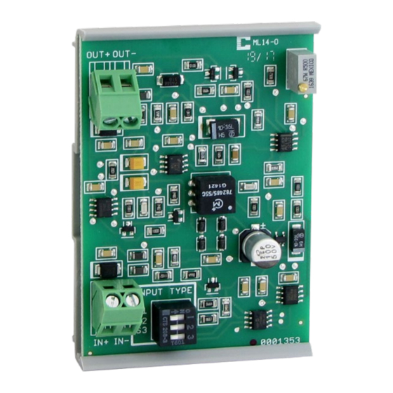
The analog input signal is connected to the IN+ and IN- terminals and the analog output signal is connected to the OUT+ and OUT- terminals. The
input and output signals are completely isolated from each other.
Factory Configurations
The Isolation Module is preset for 4-20 mA input / 4-20 mA output. The input signal may be changed by using the DIP switches as shown in Figure 5.
Calibration
The isolator is factory calibrated to ±0.1% accuracy on the 0-5 vdc input type. Using any other range will result in a transfer accuracy or <±1%. If a higher
accuracy signal is required simply apply the full-scale input signal and adjust the output signal to 20.00 mA using the calibration pot.
3/4
Figure 5 Wiring Diagram.