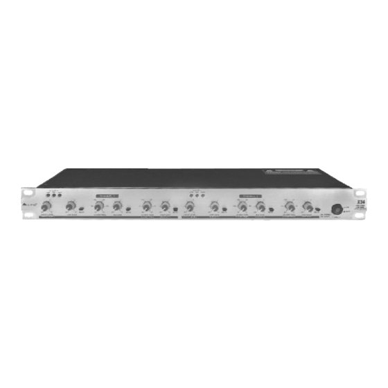
Alto X34 Manuel de l'utilisateur - Page 7
Parcourez en ligne ou téléchargez le pdf Manuel de l'utilisateur pour {nom_de_la_catégorie} Alto X34. Alto X34 12 pages. 3-way stereo/4-way mono active crossover
Également pour Alto X34 : Manuel de l'utilisateur (13 pages)

b. Supplementary Descriptions for The Rear Panel
Fuse holder & AC inlet ( 22 & 23 )
This is a dual voltage unit. Before you attempt to connect and operate the unit, please make sure that
your local voltage matches the voltage on the fuse-holder cover.
Caution: The fuse protecting the AC supplies circuits of this unit. The fuse can only be changed by a
qualified technician, in the event of a fault or changing the supply voltage. If the fuse continues to
blow after replacing, discontinue use of this unit before repaired.
The fuse-holder above the AC connector on the rear of the chassis has 3 triangular markers (please refer
to
the above pictures), with
Voltage printed next
T
o change,
pull fuse-holder out and rotate 180 ,then push in again.
Inputs & Outputs ( 24 & 26, 28, 30 for Ch1 and 31 & 34, 36, 38 for Ch2 )
All inputs and outputs are floating and balanced when connected to other floating and balanced equipment.
Any combination of balanced and unbalanced operation is permitted. ( see also " Audio Connection " )
CD Boost ( 25 for Ch1 and 33 for Ch2 )
The Constant Directivity horn equalization circuit is to be used with horns that require a high frequency
boost, to smooth the high frequency response of the sound system. The provided boost is [email protected]
rising 6dB per octave to 22.5kHz.
Consult your horn manufacturer to determine whether it is needed in your circumstance.
No changes need to be made to operate without the constant directivity boost.
If the constant directivity equalization circuit is desired on a particular channel then depress the
corresponding switch labeled " CD BOOST" . There is one switch for each channel located near to the
input socket. If two or more channels are ganged together, then use only the switch near to the used
input socket. ( the switch near to the unused input socket has no effect on the circuit when ganged ).
Phase inversion (27, 29, for Ch1 and 35,37 for Ch2)
These phase inversion switches reverse the audio signal's phase by 180 . Normally, you
won't need this switch, however, in some cases, it might be necessary. For example, the inversion
of the pins of the XLR connector may be necessary to alter the audio phase to compensate for
phase cancellation.
Mode switch (32)
This switch sets the operational mode of this unit. When it is pressed, this unit is in the state of mono
application, you can operate it as a 4-way mono crossover (high/mid/ low/ sub).
Otherwise, this unit is in the state of stereo application, you can operate it as a 3- way stereo crossover
(high/mid/low).
4. INSTALLATION & CONNECTION
4.1 Mains Connection
Please ensure that the
the power cord into the wall outlet , use the same fuse as marked on the fuse holder at the AC power
connection socket.
The mains connection of the
a standard IEC receptacle. It meets all of the international safety certification requirements.
4.2 Audio Connection
The
LTO X34 Active Crossover
ways to support a variety of applications without any signal loss.
110-120V
220-240V
THIS IS SET FOR
110V AC TO 120V
AC OPERATION
two of these triangles opposing each other, your unit is set to the
to these markers.
LTO X34 Active Crossover is set to the correct supply voltage before plugging
LTO X34 Active Crossover is made by using the enclosed mains cable and
presents with balanced XLR connectors, and it can be interfaced by several
220-240V
110-120V
THIS IS SET FOR
220V AC TO 240V
AC OPERATION
6
operating
