AkitikA STEREO 410 Manuel de démarrage rapide - Page 7
Parcourez en ligne ou téléchargez le pdf Manuel de démarrage rapide pour {nom_de_la_catégorie} AkitikA STEREO 410. AkitikA STEREO 410 11 pages. Pc30 replacement

Figure 2-The Cathode or negative lead of an LED is nearest the flat side of the package
Note that the LED1 and LED2 silk-screens have a + sign making the ANODE or positive
side of the LED.
Figure 3-Locating LED Cathode and Anode on the PCB
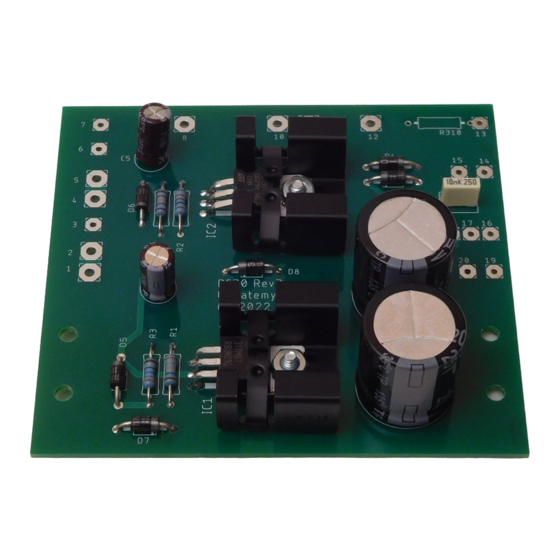
Regulator Installation
Now you'll install IC1 and IC2, the Positive and Negative regulators, along with their
heatsinks. You'll use 4-40x5/16" Philips head screws, 4-40 keps nuts, and thermal
compound.
Desig Value
IC1
LM317 adjustable positive regulator
IC2
LM337 adjustable negative regulator
Refer to the cover illustration for assembly details. Double check that the regulator type
matches the silk screen location. Spread a thin film of thermal compound on the back of
each regulator before installing it onto the heatsink and screwing the assembly down to
the board.
Done
Page 7 of 11
