esera automation 11208 Manuel de l'utilisateur - Page 3
Parcourez en ligne ou téléchargez le pdf Manuel de l'utilisateur pour {nom_de_la_catégorie} esera automation 11208. esera automation 11208 7 pages. Analog output 0-10vdc for 1-wire bus system

Art. No. 11208
7
LED indicator
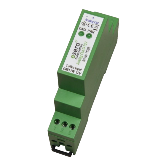
The module has a green LED display which lights up when the module is supplied with 12V supply voltage.
Display
Designation
LED green
PWR
LED green
Data
8
Connection plan
The connection diagram is available in our web-shop as a separate
document.
Module topside:
(analog output)
4 = negative output
5 = analog output
Module bottom side:
1-Wire Bus
1 = GND (Ground)
2 = 1-Wire data (5V signal level)
3 = +12V voltage
All rights reserved. Reproduction as well as electronic duplication of this user guide, complete or in part, requires the written consent of
ESERA GmbH. Errors and technical modification subject to change. ESERA GmbH, ESERA-Automation 2020
www.esera.de
Function
Display for supply voltage
Flashing when new data value is received and output (data update)
After switching on the supply voltage, the module starts in Start Up Mode.
When a voltage value of less than 10V has been output once, it switches to
normal operation.
Start Up Mode:
LED flashes after switching on the supply voltage.
Output voltage in this operating mode is 0V.
Normal operation:
Lights up permanently in normal mode
11208 V2.0 R1.0 Manual
Page 3 of 7
