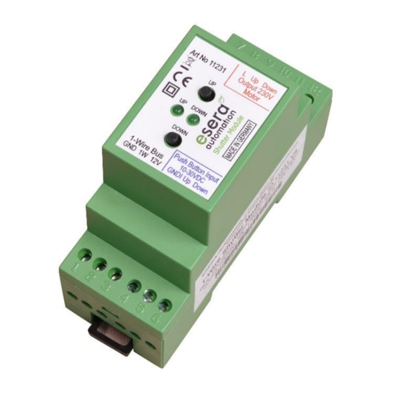
esera automation Shutter Pro V4 Manuel de l'utilisateur - Page 4
Parcourez en ligne ou téléchargez le pdf Manuel de l'utilisateur pour {nom_de_la_catégorie} esera automation Shutter Pro V4. esera automation Shutter Pro V4 7 pages. For external roller shutters, awnings, blinds or venetian blinds and 1-wire bus system w/auto-e-connect

8
Changing the roller shutter / blind operating mode
The Shutter Pro has two operating modes, which differ in the functions of manual operation (push-buttons up
and down on module topside) and the external interface (push-button interface). The difference is that the shutter
operating mode also has a push-button function to tilt the slats (see table LED display, push-button/inputs, no. 6)
This operating mode can only be selected when using the buttons on the top of the module.
How to change the operating mode?
Press the two buttons on the top of the module (UP and DOWN buttons) at the same time for about 2 seconds.
The two LEDs "UP" and "DOWN" will flash twice and will then show the current operating mode for
approx. 3 seconds.
By pressing the buttons UP and DOWN at the same time again, the operating mode will change.
LED "UP" is lit
= operating mode with tilting function for blinds and slat curtains
LED "DOWN" is lit = operating mode for roller shutters and awnings, as-delivered condition.
The selected operating mode remains permanently stored in the module, but can be changed as required.
9
Functional description 1-Wire interface, Push Buttons and Control Inputs
All three interfaces, manual operation module top, 1-wire bus interface and external control inputs work in parallel
on the motor output. A motor switched on e.g. by the 1-Wire Bus interface can be stopped by operating the
manual operation or pulse via the external control inputs. The same applies to manual operation or the external
control inputs.
If the motor of a roller shutter is to stop at a certain window position, time control by the control software must be
provided via the bus interface in automatic mode.
The Shutter Pro automatically stops driving in both directions after approx. 120 seconds by switching off the
safety motor.
Within the Shutter Pro module a microcontroller takes over the management of the manual operation, all
interfaces and the control of the relays incl. pause function and safety shutdown. The relays are electronically
connected in such a way that upward and downward operation is never switched simultaneously.
The query of the external interface reacts to status change and pressure duration.
Further details on the ESERA roller shutter system can be found on our website. You will find the information
under the keyword "Roller shutter control".
10
Software / Control 1-Wire interface
The device is controlled by DS2408 1-Wire commands. The status of the output and digital input is reported via
the 1-Wire interface.
The ESERA 1-Wire Controller features special commands for easy control of the Shutter Pro.
Available 1-Wire commands:
Read ROM
Match ROM
Search ROM
Skip ROM
Read PIO Registers
Channel Access Read
Channel Access Write
11
Control via 1-Wire Controller / 1-Wire Gateway, as of firmware 1.20_26
The 1-Wire interface of the Shutter Pro is controlled by standard commands for the DS2408 device. The relays
switched via manual operation or manual mode can be read back via the 1-Wire interface. The Shutter Pro can
easily be controlled via a 1-Wire Controller / 1-Wire Gateway. The following command is available for this
purpose.
New for this shutter module is a time control, which is executed by the module itself. It is now possible to execute
the run time (Up or Down) by command without preset and with time. Details see below.
Switching a Shutter Pro output without time function
To switch the relay output of the Shutter Pro, use the following command for the 1-Wire Controller or ESERA
Station to set only the selected function 1 = Down, 2 = Up, and 3 = Stop.
Command: SET,OWD,SHT,OWD-Number, Value
Example: set,owd,sht,2,1 => OWD Number 2 will be switched to „DOWN".
After switching the output, the new state is output as confirmation via the 1-Wire interface. The output value 0
corresponds to the rest position of the Shutter Pro.
All rights reserved. Reproduction as well as electronic duplication of this user guide, complete or in part, requires the written consent of
ESERA-Automation or E-Service GmbH. Errors and technical modification subject to change. ESERA-Automation, E-Service GmbH 2020
www.esera.de
33h
64-BIT ROM, RC-FLAG
55h
64-BIT ROM, RC-FLAG
F0h
64-BIT ROM, RC-FLAG
CCh
RC-FLAG
F0h
PIO Register
F5h
Input und Output Status
5Ah
Port Output Latches / Status
11231 V2.0 R1.0 Manual
Page 4 of 7
