esera automation DE30249510 Manuel de l'utilisateur - Page 2
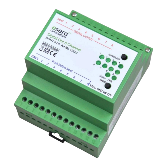
Parcourez en ligne ou téléchargez le pdf Manuel de l'utilisateur pour {nom_de_la_catégorie} esera automation DE30249510. esera automation DE30249510 7 pages. 8-fold switch module with pushbutton inputs for 1-wire bus

3
Auto-E-Connect® Support
The ESERA Auto-E-Connect® 1-Wire Plug and Play system will be used for the
1-Wire Bus supported. This enables fully automatic configurations of 1-Wire sensors
and actuators on the 1-Wire bus. It is optimized for industrial applications and
enables significant added value beyond the sensor and chip data.
The Auto-E-Connect function automatically recognizes ESERA chips, sensors and actuators, starts suitable
libraries and outputs fully formatted data.
The Auto-E-Connect functionality will be available from mid 2020 via 1-Wire Controllers, 1-Wire Gateways and
1-Wire ECO from ESERA available.
Further information on ESERA Auto-E-Connect can be found on the ESERA website, ESERA Config-Tool 3, or in
the download area for this article in the ESERA Webshop.
4
Technical data
Switching channels:
Switching voltage:
Switching current/Power :Max. 8A continuous current per output and maximally 1840VA continuous power at
Fuses:
Data interface:
Interface:
Operating voltage:
Power consumption12V: Idle state, no output relay active: ca 10mA
Pushbutton interface:
Connection:
5
conditions
Ambient
Temperature, operation: 0 °C up to +50 °C
Air humidity:
Dimensions:
Protection class:
Protection type:
Insulation strength:
All rights reserved. Reproduction as well as electronic duplication of this user guide, complete or in part, requires the written consent of
ESERA GmbH. Errors and technical modification subject to change. ESERA GmbH, ESERA-Automation 2020
www.esera.de
8, normally open contact Relay (NO contact)
Max. 250V DC or AC voltage
resistive load. Minimum load 10mA
Maximum 10A current in sum for all outputs
For capacitive or inductive loads, appropriate additional circuits, such as spark
quenching capacitors, must be provided. The max. current and power are reduced with
non-resistive loads.
External back-up fuse with 10A recommended
1-Wire Bus (12V, data and load)
1-Wire DS2408 command set
12VDC (+/-10 %)
All outputs active: ca 160mA
8 digital- /binary inputs, pulse input e.g. for pushbutton switch (closing contact)
Pulse duration min. 40ms
Input voltage 10-30VDC, max. 10mA per input, common ground.
Inputs isolated from 1-Wire interface and power supply.
The cable length between module and button is not critical, but should not exceed 30m.
Screw terminals (up to 2,5qmm wire cross section)
:
10 – 92 % (non-condensing)
70 x 90 x 70mm (WxHxD)
II
IP20
500VAC output to 1-Wire Bus, 250VAC output to output
11220 V2.0 R1.0 Manual
Page 2 of 7
