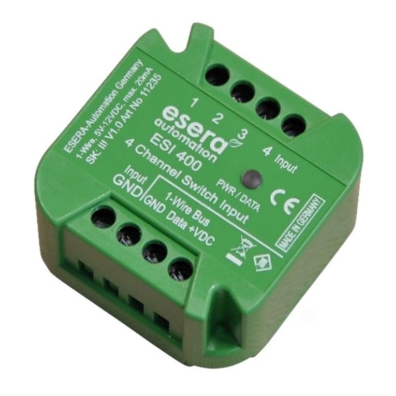
esera automation ESI 400 Manuel de l'utilisateur - Page 4
Parcourez en ligne ou téléchargez le pdf Manuel de l'utilisateur pour {nom_de_la_catégorie} esera automation ESI 400. esera automation ESI 400 6 pages. 4-channel switch input, 4-way switch input for 1-wire bus

8
LED display and operating elements
The ESI400 has a green LED for each input channel that lights up when the module is supplied with 5-12V DC. At
startup, the software version and revision of the device software are displayed by a view code (first the version
and then the revision). After about 10 seconds the ESI400 module is ready for operation.
Display
Designation
LED Green
PWR / DATA
9
Software / Control
The 1-Wire interface of the ESI400 is read out via 1-Wire command for the 1-Wire device DS2408.
The module is a standard module for many systems and software programs, such as 1-Wire controller,
1-Wire gateway, ESERA STATION, PowerDog, SmartOne, FHEM, OWFS, IP-Symcon etc.
9.1
Data output 1-Wire Controller / 1-Wire Gateway / ESERA Station-200
The 1-Wire interface of the ESI400 is controlled by standard commands for the DS2408 read.
For the ESI400 the following data is output for the binary / digital inputs.
The input value is output as decimal value 0-254 and in a second data set with binary display (0 and 1). Each
input has a value which is added up.
Input value:
Input 1 = bit 1 (value 1), input 2 = bit 2 (value 2), input 3 = bit 3 (value 4), input 4 = bit 4 (value 8), bits 5 - 8 are
static 0.
You can assign Art.No.11235 to the DS2408 device via the config tool. After assigning the part number, you will
receive formatted output.
Data output:
1_OWD1_1|2
1_OWD1_2|00000010
For further information on the possibilities and commands, refer to the current documentation
1-Wire Controller /1-Wire Gateway.
10
Operating Conditions
The module may only be operated at the voltages and ambient conditions specified for it. The device can be
operated in any position. The device is intended for use in dry and dust-free rooms.
If condensation forms, wait at least 2 hours for the device to acclimatise.
Assemblies and components must not be handled by children!
The modules may only be put into operation under the supervision of a qualified electrician.
In commercial facilities, the accident prevention regulations of the Association of Industrial Employers' Liability
Insurance Associations for electrical systems and equipment must be observed.
Do not operate the module in an environment in which flammable gases, vapours or dust are or may be present.
11
Assembly
The installation site must be protected against moisture. The device may only be used in dry indoor and protected
outdoor areas. The device is intended for mounting inside a switch cabinet as a stationary device.
12
Disposal note
Do not dispose of the device in household waste! Electronic devices must be disposed of in
accordance with the Directive on Waste Electrical and Electronic Equipment on local
Dispose of at collection points for old electronic equipment!
All rights reserved. Reproduction as well as electronic duplication of this user guide, complete or in part, requires the written consent of
ESERA GmbH. Errors and technical modification subject to change. ESERA GmbH, ESERA-Automation 2020
www.esera.de
Function
The LED has a double function
lights permanently, display for power supply
flashes when the status of the inputs changes
=> Controller No._Module No._Data set | Decimal Value Input
=> Controller No._Module No._Data set | Binary Display Input
11235 V2.0 R1.0 Manual
Page 4 of 6
