EDI LMD224 Manuel d'utilisation - Page 9
Parcourez en ligne ou téléchargez le pdf Manuel d'utilisation pour {nom_de_la_catégorie} EDI LMD224. EDI LMD224 14 pages. Inductive loop monitor

2.4.2 RETUNE OR RESET A CHANNEL
Press the MODE and FREQ buttons simultaneously to reset the channel. This will clear any
previous loop fault indication and cause the channel to retune.
2.4.3 FACTORY DEFAULT SETTINGS
Press the Channel 1 MODE and FREQ buttons simultaneously while first applying power to
the unit to reset all channels to the factory default settings.
2.5 LOOP FAULT MONITORING
The LMD Series Loop Monitor continuously checks the integrity of the loop. The system is
able to detect open circuit loops, shorted loops, or sudden changes in inductance
exceeding 25% of the nominal inductance.
2.5.1 CURRENT FAULT
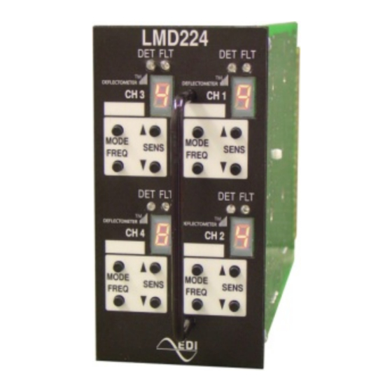
If a fault is detected, both the DET (Red) and FLT (Yellow) LEDs continuously emit a
sequence of flashes and the DEFLECTOMETER will display the letter "F". Each type of
fault is identified by a different flash sequence followed by a one second pause:
Flash Sequence
1 flash
2 flashes
3 flashes
2.5.2 PREVIOUS FAULT
If the fault condition is removed, the DET indicator and the channel output will return to
normal operation. The FLT indicator will continue to flash indicating that a fault had
previously occurred. This Previous Fault indication may be reset by momentarily pressing
the MODE and FREQ buttons simultaneously. See section 2.4.2.
Eberle Design Inc.
LMD222 and LMD224 Series
Operations Manual
Factory Defaults
Sensitivity Level
Operational Mode
Frequency Level
Open Circuit Loop (or Inductance too high)
Shorted Circuit Loop (or inductance too low)
>25% Change in Inductance
6
Short Presence
High
Fault
Page 6
