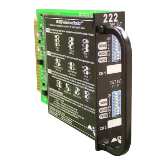
EDI 222 Series Manuel d'utilisation - Page 12
Parcourez en ligne ou téléchargez le pdf Manuel d'utilisation pour {nom_de_la_catégorie} EDI 222 Series. EDI 222 Series 17 pages. Inductive loop detector sensor unit

1.8.1 MECHANICAL
Height ................................................................................................................... 4.50 inches
Width ................................................................................................................... 1.12 inches
Depth (excluding handle) .................................................................................... 6.875 inches
1.8.2 ENVIRONMENTAL
Storage Temperature Range ............................................................................ -45 to +85
Operating Temperature Range ......................................................................... -34 to +74
Humidity Range (non-condensing) ............................................................. 0 to 95% Relative
1.8.3 ELECTRICAL
DC Supply Voltage Minimum .................................................................................... 10.8 Vdc
DC Supply Voltage Maximum ................................................................................... 28.8 Vdc
DC Supply Current ...................................................................................... 80 mA Maximum
Optically Isolated Solid State Outputs
True (low, 50 mA) ................................................................................... less than 1.5 Vdc
Maximum Leakage Current (DC Supply = 24Vdc) ..................................................... 1 uA
Maximum Current (low) ........................................................................................... 50 mA
Isolation ............................................................................................... exceeds 5000 VAC
Connections:
Edge Connector mates with connector type Cinch 50-44A-30.
Note: Pins M & 11, N & 12, P & 13, R & 14, S & 15, T & 16, U & 17, V & 18, Y & 21, Z & 22
have no connection.
Eberle Design Inc.
Model 222
Operations Manual
PIN
FUNCTION
A
Logic Ground
B
+24 VDC
C
Reset
D & 4
Loop Input CH 1
E & 5
Loop Input CH 1
F
CH 1 Output Collector
H
CH 1 Output Emitter
J & 8
Loop Input CH 2
K &9
Loop Input CH 2
L
Chassis Ground
W
CH 2 Output Collector
X
CH 2 Output Emitter
o
C
o
C
Page 10
