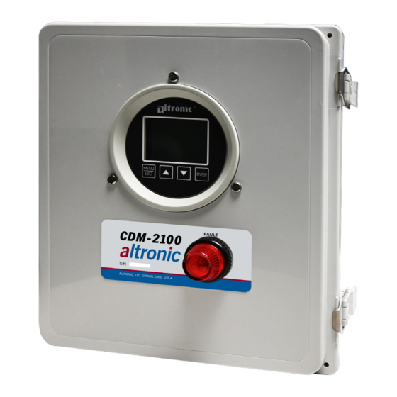
Altronic CDM-2100 Manuel d'utilisation - Page 10
Parcourez en ligne ou téléchargez le pdf Manuel d'utilisation pour {nom_de_la_catégorie} Altronic CDM-2100. Altronic CDM-2100 20 pages. Differential pressure monitor

9.0 RS-485 COMMUNICATIONS
The CDM-2100 gauge is part of a system that has been carefully designed to
easily interface to popular computers, terminals, programmable controllers and
Altronic instruments. The gauge communicates in the Modbus RTU protocol.
9.1
MASTER/SLAVE OPERATION:
The gauge's RS-485 communication system is designed as a master/slave
system; that is, each unit responds to its own unique address (node number)
only after it is interrogated by the master (computer). One master and up to 32
slaves can communicate in the system. The units communicate with the master
via a polling system. The master sends a command and only the polled slave
responds. The slave modules can never initiate a communications sequence. A
simple command/response protocol must be strictly observed.
9.2 NODE NUMBER:
The node number is used in the system to identify the desired slave unit being
polled. The node number can be any numeric value from 1 to 99 although
only 32 devices can be served on a single communications port. This number
range (1 to 99) is allowed so that if device grouping by function or application
is desired, it can be implemented using the first digit as the group or engine
number and the second as the unit number. For example, 53 could be used to
identify the number 3 slave unit mounted on engine number 5.
9.3 BAUD RATE:
Baud rates available are 9600, 19200, 38400, 57600, 115200.
9.4 HALF-DUPLEX OPERATION:
The RS-485 system employed uses two wires for communication and cannot
send and receive data at the same time over the same two wires making it a
half-duplex system. When the master is in the transmit mode, the slave is in the
receive mode and vice-versa.
9.5 ELECTRICAL OPERATING RANGE:
RS-485 is a communications standard to satisfy the need for multi-dropped
systems that can operate at high speeds over long distances. RS-485 uses a
balanced differential pair of wires switching from 0 to 5 volts to communicate
data. RS-485 drivers can handle common mode voltages from -7 to +12
volts without loss of data, making them an excellent choice for industrial
environments.
9.6 COMMUNICATIONS PARAMETERS:
The following must be set by the master to communicate with the slaves:
Baud Rate:
9600 (DEFAULT) others available, see section 10.3
Data Bits:
8
Stop Bits:
1
Parity:
None
9.7
COMMUNICATIONS WIRING:
The RS-485 wiring diagram illustrates the wiring required for multiple slave
unit hookup. Note that every slave unit has a direct connection to the master.
This allows any one slave unit to be removed from service without affecting
the operation of the other units. Every unit must be programmed with a unique
address or node number, but the addition of new units or nodes can be in
any order. To minimize unwanted reflections on the transmission line, the bus
should be arranged as a trunk line going from one module to the next. Random
structures of the transmission line should be avoided. Special care must be
taken with long busses (500 feet or more) to ensure error-free operation. Long
busses must be terminated with a 120 ohm resistor between the terminals
marked RS-485 A and RS-485 B at the master only. The use of twisted pair
shielded cable will enhance signal fidelity and is recommended. To prevent
ground loops, the shield should be connected to the shield terminal at the
master only.
CDM-2100 OM 3-21
All rights reserved © ALTRONIC, LLC 2021
10
