Altronix AL1012ULM Manuel d'installation - Page 9
Parcourez en ligne ou téléchargez le pdf Manuel d'installation pour {nom_de_la_catégorie} Altronix AL1012ULM. Altronix AL1012ULM 17 pages. Multi-output access control power supply/chargers
Également pour Altronix AL1012ULM : Manuel d'installation (17 pages), Manuel d'installation (17 pages)
Unit should be tested at least once a year for the proper operation as follows:
Output Voltage Test: Under normal load conditions the DC output voltage should be checked for proper voltage level
(Output Voltage and Stand-by Specification Charts, pg. 4).
Battery Test: Under normal load conditions check that the battery is fully charged, check specified voltage at the battery terminals
and at the board terminals marked [+ BAT --- ] to ensure that there is no break in the battery connection wires.
Note:
AL300ULXB2, AL400ULXB2, AL600ULXB and AL1012ULXB (Power Supply Board) maximum charge current is 0.7A.
AL1024ULXB2 (Power Supply Board) maximum charge current is 3.6A.
Expected battery life is 5 years; however, it is recommended to change batteries within 4 years or less if necessary.
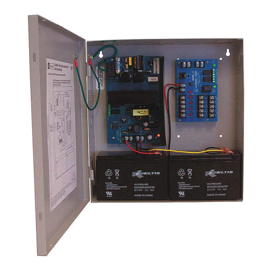
Power Supply Board
LED
Red (DC)
Green (AC)
ON
ON
ON
OFF
OFF
ON
OFF
OFF
Red (Bat)
Battery Status
ON
Normal operating condition.
OFF
Battery fail/low battery.
MOM5 - Output Module
LED
ON
Power (Green)
Normal operating condition.
Trigger (Green)
Input is triggered (alarm condition).
Outputs (Red)
Output tripped due to a short circuit or overload condition.
M series
Maintenance:
LED Diagnostics:
Power Supply Status
Normal operating condition.
Loss of AC. Stand-by battery supplying power.
No DC output. Short circuit or thermal overload condition.
No DC output. Loss of AC. Discharged battery.
OFF
Power failure.
No input trigger (non-alarm condition).
Normal operation.
- 9 -