Custom Dynamics MagicFLEX2 Indian LED War Bonnet Light Kit Manuel d'instructions d'installation - Page 2
Parcourez en ligne ou téléchargez le pdf Manuel d'instructions d'installation pour {nom_de_la_catégorie} Custom Dynamics MagicFLEX2 Indian LED War Bonnet Light Kit. Custom Dynamics MagicFLEX2 Indian LED War Bonnet Light Kit 2 pages.

4.
Remove the unserviceable LED horseshoe puck housing from behind the War Bonnet lens.
5.
Place one piece of provided heat shrink tubing over the red and black wires of the MagicFLEX2 LED strip. Using the
provided 22 AWG wire, attach red wire to red wire and black wire to black wire by soldering or twisting the wires togeth-
er. Slide the heat shrink for the Red wire over the connection and apply heat using a hair dryer or heat gun until heat
shrink has shrunk around connection. Repeat process for the black wire.
6.
Apply 3M® primer on the front of the LED horseshoe puck housing. Allow to dry.
7.
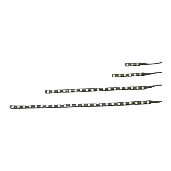
Remove the red protective tape from the back of the MagicFLEX2® LED and press into place.
8.
Reassemble the War Bonnet Light and install on the fender.
9.
Attach the MagicFLEX2® LED light strip wire harness with the War Bonnet wire harness.
10. Re-install the front fender. Refer to your service manual for fender installation instructions.
11. Continue routing the MagicFLEX2® LED light strip wire harness back to a central point near battery compartment under
seat. Route wires such that they not interfere with normal operation of bike. Cut off any excess wires, strip back insula-
tion as required.
12. Secure wires to the frame using some of the tie wraps provided.
Note: If installing with Indian Engine Accent Light Kit (M2EK1-IND), stop here and follow the wiring instructions for
that kit.
13. Connect the Black wire to the bike's ground or the ground terminal of the battery.
14. Connect the Red wire to a on/off switch that is connected to a fused connection to the positive side of the battery. Take
necessary precautions when making connection and refer to bike's owner's manual.
Caution: DO NOT allow any tools to touch both positive (+) side of battery and any metal surface on bike as it will cause a
short which could result in serious injury and damage to the battery or other electrical circuits.
15. Secure any remaining wires with tie wraps.
16. Turn on switch and check operation of all lights.
Questions? Call us at: 1 (800) 382-1388
Installation Instructions - Page 2
Wiring Diagram
(Optional)
(Required)
Connector
M-TH 9AM-6PM / FR 10AM-6PM EST
Either ground
(-)
Connector
(Required)
12-2017
