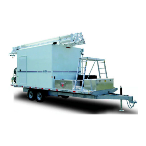
Aluma Tower Company TM51-35 Manuel d'instructions - Page 8
Parcourez en ligne ou téléchargez le pdf Manuel d'instructions pour {nom_de_la_catégorie} Aluma Tower Company TM51-35. Aluma Tower Company TM51-35 12 pages. Tower setup with guy wires includes guying to outriggers

7.
Snug the remaining guy wires by starting at the lowest set. Be careful in
tightening the wire and check to be sure the tower remains aligned and level. The
lowest set of guy wires can be tightened securely; the remaining sets should only
be snugged loosely.
THE TOWER IS NOW READY FOR USE.
ERECTING THE TOWER AT LESS THAN FULL HEIGHT
In some instances, erecting the tower at less than it's full height may prove to be adequate
for desired communications. NOTE: All of the color coded guy wires WILL NOT be
attached to the corresponding color coded guy ears when using this method.
1.
For the Tower Models having 3 sections:
Attach the blue color coded ends of the guy wires to the corresponding blue color
coded guy ears at the top of the bottom section of the tower. Attach the yellow
color coded ends of the guy wires to the red color coded guy ears at the top of the
top section of the tower, using the screw pin shackle (see Fig. 6). Be sure to
tighten the screw pin shackle with a wrench. Lay the appropriate sets of three
each guy wires in the general direction to which they will be anchored. (DO
NOT attach guy wires to the middle section of the tower).
Continue with directions "Erecting the Tower at Full Height" with one
exception; stop raising the tower when the top guy wires become taut. Do not
over extend the tower.
2.
For the Tower Models having 4 sections:
Attach the green color coded ends of the guy wires to the corresponding green
color coded guy ears at the top of the bottom section of the tower. Attach the blue
color coded ends of the guy wires to the red color coded guy ears at the top of the
top section of the tower, using the screw pin shackle (see Fig. 6). Be sure to
tighten the screw pin shackle with a wrench. Lay the appropriate sets of three
each guy wires in the general direction to which they will be anchored. (DO
NOT attach guy wires to the middle section of the tower).
Continue with directions "Erecting the Tower at Full Height" with one
exception; stop raising the tower when the top guy wires become taut. Do not
over extend the tower.
LOWERING THE TOWER
1.
To start the procedure of lowering the tower, it is first very important to slacken
all guy wires except the lowest set. Crank the tower up slightly to allow the safety
stop to swing out of the way. The safety stop is controlled by a orange cord
attached to one leg of the tower. After the tower has been cranked up slightly, pull
the orange cord until the safety stop clears the rung above it. Start lowering the
tower while keeping tension on the orange cord. The safety stop must be kept out
of the way for the complete lowering of the tower.
2.
After the tower has been lowered to the retracted position, be sure to reattach the
"Red Safety Strap" around the inner section(s).
2/13/2012
Page 7
TRAILER TOWER SETUP INSTRUCTIONS-GUYED TO OUTRIGGERS
