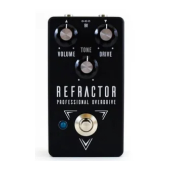
Aion Electronics Refractor Overdrive Manuel - Page 5
Parcourez en ligne ou téléchargez le pdf Manuel pour {nom_de_la_catégorie} Aion Electronics Refractor Overdrive. Aion Electronics Refractor Overdrive 8 pages. Klon centaur professional overdrive

General Build Instructions
These are general guidelines and explanations for all Aion Electronics DIY projects, so be aware that not
everything described below may apply to this particular project.
Build Order
When putting together the PCB, it's recommended that you do not yet solder any of the enclosure-mounted
control components (pots and switches) to the board. Instead, follow this build order:
1. Attach the audio jacks, DC jack and footswitch to the enclosure.
2. Firmly attach the pots and switches to the enclosure, taking care that they are aligned and straight.
3. Push the LED
into the hole in the enclosure with the leads sticking straight up, ensuring that the flat side
1
is oriented according to the silkscreen on the PCB.
4. Fit the PCB onto all the control components, including the leads of the LED. If it doesn't fit, or if you need
to bend things more than you think you should, double-check the alignment of the pots and switches.
5. Once you feel good about everything, solder them from the top
there is no stress on the solder joints from slight misalignments that do not fit the drilled holes. You can
still take it out easily if the build needs to be debugged, but now the PCB is "custom-fit" to that particular
enclosure.
6. Wire everything according to the wiring diagram on the last page.
For the LED: You can use a bezel if you'd like, but generally it's easier just to drill the proper size of hole
1
and push the LED through so it fits snugly. If you solder it directly to the PCB, it'll stay put even if the hole is
slightly too big. Make absolutely sure the LED is oriented correctly (the flat side matches the silk screen) before
soldering, as it'll be a pain to fix later! After it's soldered, clip off the excess length of the leads.
Note on soldering the toggle switch(es): It will require a good amount of solder to fill the pads. Try to be as
2
quick as possible to avoid melting the lugs, and be prepared to feed a lot of solder as soon as the solder starts
to melt. I recommend waiting 20-30 seconds between soldering each lug to give it time to cool down.
"RPD" and "LEDR" resistors
The resistors marked "RPD" and "LEDR" are generally not original to the circuit and can be adjusted to
preference. "RPD" is the pulldown resistor to help tame true-bypass popping, while "LEDR" controls the
brightness of the LED. I generally use 2.2M for the pulldown resistor and 4.7k for the LED resistor.
Sockets
Since double-sided boards can be very frustrating to desolder, especially components with more than 2 leads,
it is recommended to use sockets for all transistors and ICs. It may save you a lot of headaches later on.
KLON CENTAUR / REFRACTOR OVERDRIVE
as the last step before wiring. This way
2
5
