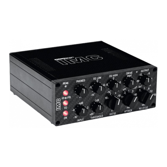
DOCtron IMC5 Manuel d'installation et d'utilisation - Page 5
Parcourez en ligne ou téléchargez le pdf Manuel d'installation et d'utilisation pour {nom_de_la_catégorie} DOCtron IMC5. DOCtron IMC5 11 pages.

The individual parts of the circuit will be described later in detail.
The general circuit description is initially limited to the Audiopath.
Since both channels are identical, only the left channel is described here, as shown in the block
diagram.
IMC5 has a so-called "true-bypass", which means that the audio signal in the de-energized state is
passed uninfluenced from input to output.
The audio signal goes via an isolated 6,3mm jack socket to the treble and bass EQ. Then the audio
signal reaches a sound-forming, discrete operational amplifier (ORANGE DD). Now the signal
reaches the VCA compressor. The output stage of the compressor reaches a further amplifier stage,
which later determines the saturation for the output transformer. The signal conditioned in this way
now reaches a balancing driver stage and finally the LUNDAHL output transformer.
At the output of the transformer, the signal is routed to the adjustable Output-Stage and to the
headphone amplifier.
The remaining circuit parts work exclusively with control voltage and are not in the audio path. Thus,
no interference can enter the signal path. The separation between audio path and control voltages is
also made by using 6-way multilayer boards with their own ground layers.
This reduces interference enormously.
New in v5 is also an external Sidechain (Send / Return on the backplane).
The power supply is via an external switching power supply. This power supply must deliver at least
20V-24V. The distribution of the positive and negative supply voltages is carried out in the device by
its own sub-switching power supplies.
Due to the conductivity of the carbon casing material, sufficient protection against the outside world
is ensured. The interior of the housing no longer needs to be sprayed with conductive ink, as with
IMC1.
The individual circuit parts in detail
The power supply:
The power supply:
The power supply:
The power supply:
The external switching power supply is plugged in with a hollow plug on the back of IMC5.
The power supply has a very large voltage and frequency range and should be universally
applicable. Please check before connecting the mains connection, if the primary connection
corresponds to the specifications on site! The power plug should be unplugged when connecting or
disconnecting the power supply to the IMC.
disconnecting the power supply to the IMC.
disconnecting the power supply to the IMC.
disconnecting the power supply to the IMC.
The internal overload fuses could trigger. If this is the case, please wait a few minutes. The fuses are
self-resetting. IMC5 has comprehensive reverse polarity protection and protection circuits against
"phantom-power". All safety devices are self-resetting. An opening of the housing is therefore not
necessary.
In general, all audio connections should be made before power is supplied to the device. In addition
to the main connector is a main switch. This switch turns the IMC5 on or off.
Here are the technical data of the external power supply used:
IMC5
The power plug should be unplugged when connecting or
The power plug should be unplugged when connecting or
The power plug should be unplugged when connecting or
5
© DOCtron 2021
