Clippard EVPD Manuel d'installation et d'utilisation - Page 3
Parcourez en ligne ou téléchargez le pdf Manuel d'installation et d'utilisation pour {nom_de_la_catégorie} Clippard EVPD. Clippard EVPD 3 pages. Proportional valve driver

Fault Codes
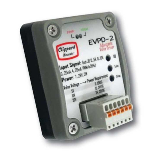
Indicators
The EVPD has two LEDs. A
of suffi cient voltage is properly connected to the board. The
green
LED is for status and faults. Its functionality is described
below:
Normal Conditions
Under normal conditions (no faults) the
the command is larger than the command dead band
(command value at which the driver starts supplying current).
3 Blinks
If the voltage command is more than 29.2 volts, the driver will
be operating in the fault mode. The PWM output is forced to
zero and disable. While in high voltage fault, the
blink 3 times, pause for 1.5 seconds, and then start blinking
again. If the Voltage command drops under 29.2 volts, the driver
will return to working normally.
red
LED indicates that a power signal
green
LED is on when
green
EVPD PROPORTIONAL VALVE DRIVER
Installation & Operations Manual
4 Blinks
If the power supply voltage is less than 6.5 volts, the driver
will also be in the fault mode, the LED will blink 4 times,
pause for 1.5 seconds and then begin blinking again. The
same will occur if the outputs (M+ and M-) are shorted, or
if the driver is overheating. These 3 faults have the same
visualization process (4 blinks).
Once in fault mode, the driver will remain in fault mode
until the condition causing the fault is corrected. The driver
tests for the fault every 5 blinking cycles assuming the
driver has been set-up properly (correct power supply,
wiring and command signal). The only possible "unknown
fault" may be a noise command signal with amplitude in
the range of the Command Dead Band (CDB) setting. Since,
when in normal operation the status LED is programmed
to be ON when the command is bigger than the CDB, and
OFF otherwise, a noisy signal around the CDB may cause
the LED to blink randomly.
LED will
A quick way to determine whether the driver is actually
visualizing a fault condition, is to measure the voltage
across the valve (V+ and V-) and change the command to
a value larger than the CDB . If the output voltage remains
zero regardless of the command input, it is a fault, and
should blink 3 or 4 times. If the voltage changes with the
command, the driver is not detecting any fault as
described herein.
877-245-6247 |
CLIPPARD INSTRUMENT LABORATORY, INC. • ISO 9001:2015
clippard.com
