ASG DTT-50 Manuel d'utilisation - Page 4
Parcourez en ligne ou téléchargez le pdf Manuel d'utilisation pour {nom_de_la_catégorie} ASG DTT-50. ASG DTT-50 12 pages.

To use place the unit on a smooth, flat, level surface. Clamp the unit using the
optional calibration / mounting bracket if higher torques are to be used.
To attach the bracket, remove the screws holding the 4 rubber feet found on each
corner of the unit. The back plate is held in place by 2 more mounting screws. DO
NOT REMOVE THESE SCREWS, OR REMOVE THE BACK PLATE OR THE
WARRANRY IS VOIDED. The bracket may be mounted with the clamping knobs at
the top of the unit, or at the bottom of the unit. Replace the screws and rubber feet to
retain the bracket. Do not over tighten and distort the rubber feet.
CAUTION DTT-500 and later versions of the DTT-200 have a built in mounting
bracket. Firmly bolt the DTT-200 and the DTT-500 to a level surface such as a
bench or wall bracket to prevent injury.
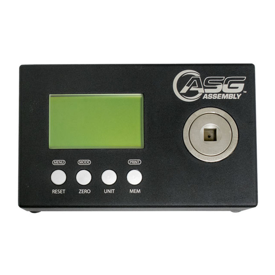
Select the proper torque units. The unit will default to lbf.in when you turn it on. You
can use the "UNIT" button to scroll through the available units until you find the one
you want. If the unit "wakes up" reading units other than lbf.in that can be changed in
the system menu
If the unit is not at 0 press the "RESET / ESC" button. The unit will default to the PEAK
setting when turned on. Use the "MODE" button to change to the TRACK or FIRST
PEAK setting if desired. This function may not work with the battery charger connected
to the unit.
4)
OPERATION OF THE DTT METER WITH THE FACTORY DEFAULTS
The meter comes from the factory ready for normal operations. The POWER SWITCH,
BATTERY CHARGER CONNECTOR, and RS-232 SOCKET are on the left side of the
meter. The SERIAL NUMBER is on the back of the meter.
During normal operation, the LCD display will show: The Measurement Mode in the
upper left-hand corner of the LCD. The Measurement Units in the upper right hand
corner of the LCD. The Torque Reading in the center of the LCD, The Current Time in
the lower left hand corner of the LCD and the circle (or CW / CCW arrow) showing the
direction the torque was applied. These items are in Bold type in the display below.
This will be referred to as the operating display.
Consult the programming and calibration manual for optional features which can be
enabled. When any of those features are enabled there will be indications on the LCD
To alert you that they are enabled.
There are 4 buttons located on the front of the meter near the bottom. The buttons
perform various tasks depending on whether the meter is set to do normal operations
or if you are programming the meter.
4
