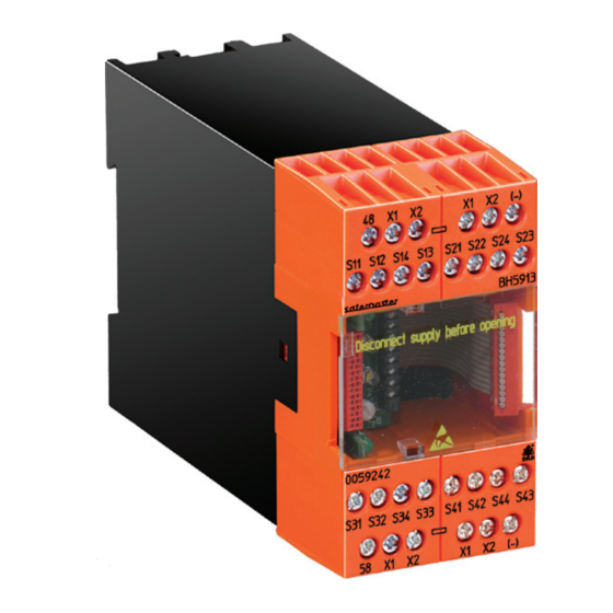
DOLD SAFEMASTER M BH 5913 Technique de sécurité - Page 12
Parcourez en ligne ou téléchargez le pdf Technique de sécurité pour {nom_de_la_catégorie} DOLD SAFEMASTER M BH 5913. DOLD SAFEMASTER M BH 5913 12 pages.

Technical Data
Voltage Supply
Nominal voltage U
:
DC 24 V (coming from the basic module
N
BH5911)
Voltage range:
with max. 5% residual ripple: 0.85 ... 1.15 U
Nominal consumption:
max. 60mA
(no load on semiconductor outputs)
Short-circuit protection
of the modules:
internally with PTC
Input
Control voltage
via X1, X2, 48.58:
DC 23 V at U
Control voltage
via S12, S14, S22, S24,
S32, S34, S42, S44:
4.5 mA each at U
Minimum voltage
on S12, S14, S22, S24,
S32, S34, S42, S44:
DC 16 V
Semiconductor outputs
Output at terminal 48 and 58: Transistor outputs, plus-connected
Output nominal voltage:
DC 24 V, max. 100 mA constant current,
max. 400 mA for 0.5 s
Internal short circuit, overtemperature, and
overload protection
reaction times (time till reaction of the assigned output):
Typ. NO time with U
:
N
Input modules
manual start
BG 5913
Emergency stop
max. 80 ms
Light barriers
max. 80 ms
or simulation:
Safety gates
max. 80 ms
Two-hand control
max. 85 ms
Break time (reaction time):
Input modules
BG 5913
Emergency stop
max. 33 ms
Light barriers
max. 33 ms
Safety gates
max. 33 ms
Two-hand control
max. 33 ms
General Data
Operating mode:
Temperature range:
Clearance and creepage
distances
rated impuls voltage /
pollution degree:
eMC
Electricstatic discharge:
HF irradiation:
E. DOLD & SÖHNE KG • D-78114 Furtwangen
e-mail: [email protected] • internet: http://www.dold.com
N
N
N
Automatic start
First start
Restart
max. 850 ms
max. 115 ms
max. 850ms
max. 115 ms
Gate closing:
max. 115 ms
Continuous operation
± 0 ...+ 50 °C
At an operating temperature of 50 °C
the modules must be mounted with
a distance of 3 - 5 mm.
4 kV / 2
IEC 60 664-1
8 kV (contact)
IEC/EN 61 000-4-2
(corresponding to test severity level 3)
10 V / m
IEC/EN 61 000-4-3
Technical Data
Fast transients:
on supply line A1-A2
on signal and control lines:
Surge voltages
between
wires for power supply:
wire and ground:
HF wire guided:
Radio interference
suppression:
Degree of protection
Housing:
Terminals:
Housing:
Vibration resistance:
Shock resistance
Acceleration:
Pulse duration:
Number of shocks:
Climate resistance:
Terminal designation:
Wire connection:
Wire fixing:
Mounting:
Weight:
BG 5913:
BH 5913:
Dimensions
Width x height x depth
BG 5913:
BH 5913:
Safety related data
Safety data for other variants are available on request
nfo
Standard type
BG 5913.08/00mF0
Article number:
BH 5913.08/00mF0
Article number:
•
POBox1251•Telephone(+49)77 23 / 654-0 • Telefax (+49) 77 23 / 654-356
12
2 kV
IEC/EN 61 000-4-4
2 kV
IEC/EN 61 000-4-4
1 kV
IEC/EN 61 000-4-5
2 kV
IEC/EN 61 000-4-5
10 V
IEC/EN 61 000-4-6
Limit value class B
EN 55 011
IP 20
IEC/EN 60 529
IP 20
IEC/EN 60 529
Thermoplastic with V0 behavior
according to UL Subject 94
Amplitude 0.35 mm IEC/EN 60 068-2-6
Frequency 10...55 Hz,
10 g
16 ms
1000 per axis on three axes
0 / 050/ 04
IEC/EN 60 068-1
EN 50 005
1 x 2.5 mm
2
stranded wire with sleeve, or
1 x 4 mm
2
massive or
2 x 1.5 mm
2
stranded wire with sleeve
DIN 46 228-1/-2/-3/-4
Box terminal with wire protection, remov-
able terminal strips.
on DIN rail
IEC/EN 60 715
193 g
255 g
22.5 x 84 x 121 mm
45 x 84 x 121 mm
DC 24 V
0055530
DC 24 V
0059242
BG 5913.08/_0_ _ _ / 11.05.09 e
