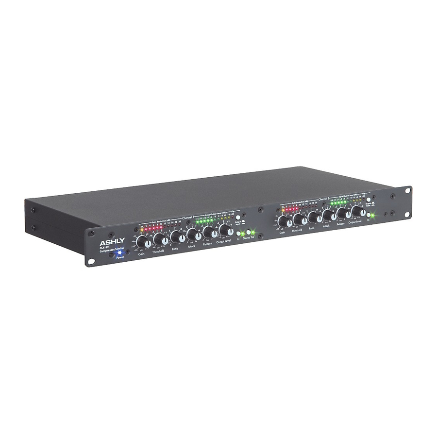
Ashly CLX-52 Manuel d'utilisation - Page 6
Parcourez en ligne ou téléchargez le pdf Manuel d'utilisation pour {nom_de_la_catégorie} Ashly CLX-52. Ashly CLX-52 12 pages. Compressor/limiter
Également pour Ashly CLX-52 : Notes techniques et spécifications (2 pages), Manuel d'utilisation (12 pages), Notes techniques et spécifications (2 pages)

Page - 6
Safety Instructions – 3
Introduction - 4
CLX-52 – 5
The CLX-52 is 1RU, and weighs 8 pounds
Connectors & Cables – 5
Physical Description - 6
Front Panel
Rear Panel
Installation – 7
Typical Applications - 8
Troubleshooting - 9
Dimensions - 9
Specifications - 10
Warranty - 11
A unique feature of Ashly Compressor/ Limiters is the incorporation of a double release-time constant. When a
conventional compressor/limiter is adjusted for slow release times, transients such as mic "pops" may cause a severe
reduction in gain followed by a slow fadeup, making the action of the limiter very obvious. With the double time constant,
release from gain reduction after a brief transient is always fast, with a slower release after a sustained overdrive.
CLX-52 Front Panel
1.
Gain - The Gain control adjusts incoming signal
level to the VCA circuit. It is always active, so
switching out the limiter function has no effect
on this control. This control should normally be
left at "0" to achieve accurate Threshold
calibration.
2.
Threshold - The Threshold control has a range
of -40 to +22 dB, allowing applications from low
level compression to high level limiting. The
Threshold control determines the audio level
above which Gain Reduction occurs. When the
signal peaks exceed the selected threshold, the
LED comes on and gain reduction is occurring.
3.
Ratio - This control determines the ratio of
change in output level to changes in input level
for signals above threshold. The numbers
printed around the Ratio control are calibrated
in db and indicate the increase in input (above
threshold) required to produce a 1db increase
in output. This can be expressed conveniently
as a ratio. If the output remains constant no
matter how high the input level, we have an
infinite ( ) input/output ratio. It should be
remembered that the Ratio control has no
effect on signals which are below threshold.
4.
Attack Time - The response of the
compressor/limiter to signal levels above
threshold is further defined by the Attack Time
control. Attack time is the amount of time that
the unit takes to attenuate the output level after
threshold has been reached. This unit provides
continuously variable attack times from 200
microseconds to 20 milliseconds.
5.
Release Time - Release time, is the time
required to restore system gain to normal after
the input signal has fallen below threshold
level. Proper release time will depend on the
type of program material being processed and
the way in which the limiter is being used.
6.
Output Level - Output Level control is provided
to fully cut or restore up to 18 dB of system
gain. For unity gain, set the control to 0.
Copyright© 2006 – Ashly Audio Inc.
Operator Manual – CLX-52 Compressor/Limiter
7.
8.
9.
10. Input/Output Meter Select - While the Gain
In/Out Switch - This switch enables you to
quickly hear the CLX compressor/limiter in or
out of the audio chain. When the switch is in
the OUT position, all limiting and compression
controls and functions are bypassed, with the
exception of the Gain and Output controls,
which continue to function.
Stereo Tie Switch - This switch allows for Gain
Reduction on a stereo signal with no
degradation of the stereo image. When pressed
in, the Stereo Tie Switch combines each
channel's internal detector outputs so that the
channel with the loudest signal will determine
the action applied to both channels. Leave this
switch out for normal operation.
Threshold/Gain Reduction Display - As soon
as the threshold level is reached, the yellow
LED illuminates. Depending on how far the
input level rises above threshold, successive
red LED's will illuminate, indicating gain
reduction. Gain Reduction can best be
described as the difference between input level
and the resulting change to output level. For
signals above threshold, output level will
increase only to the extent that the ratio control
allows.
Reduction display accurately represents the
action of the limiter, comparing input to output
levels in real time is somewhat more intuitive,
and is made simple using the Input/ Output
Meter Select switch. The Input meter takes its
signal just after the Gain control, and will
indicate input signal level regardless of CLX
output levels or limiter settings. The output
meter display takes its signal from the actual
output of the unit, so every control that affects
the output will also have an effect on output
meters. Used in conjunction with the gain
reduction meters, Input/Output meters prove to
be an extremely useful diagnostic tool when
working with system dynamics and level
control.
