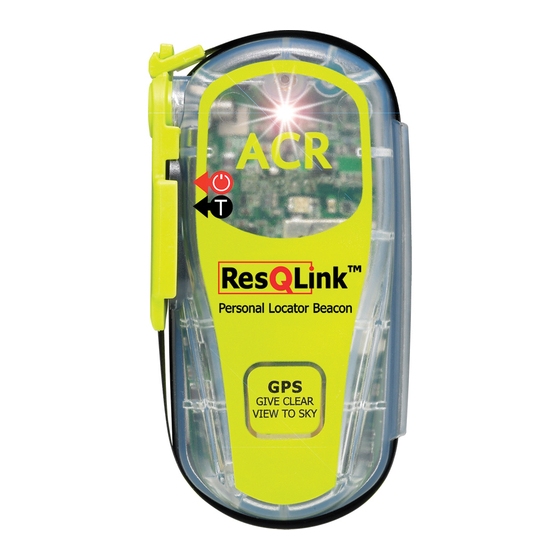
ACR Electronics ENGLISH Manuel d'assistance produit - Page 13
Parcourez en ligne ou téléchargez le pdf Manuel d'assistance produit pour {nom_de_la_catégorie} ACR Electronics ENGLISH. ACR Electronics ENGLISH 20 pages. Personal locator beacon

SECTION 2 - OPERATION
2.1
GENERAL
2.1.1 The 406 PLB and GyPSI™ 406 PLB Beacon Models are designed to be manually deployed and
activated.
2.1.2 The GyPSI™ 406 PLB Beacon can accept NMEA 0183 GPS Data (format GGA 1.5 and above)
through it's I/R interface. Data is updated every 20 minutes once an initial position is acquired.
2.1.3 The GyPSI™ 406 PLB is also designed to allow the user to perform periodic testing and
confirmation of GPS connection and downloaded coordinates.
2.1.4 The GyPSI™ 406 PLB checks for a valid GPS interface connector approximately every 2 seconds
if no current valid data exists.
2.1.5 The GyPSI™ 406 PLB can be forced to update its GPS data by initiating the self test function.
2.1.6 The GyPSI™ 406 PLB will hold the last GPS coordinates in memory until unit is activated. After
deactivating unit, GPS data is returned to default.
2.2
406 PLB AND GyPSI™ 406 PLB OPERATING INSTRUCTIONS
2.2.1 Activation
Unfold Antenna from around unit and move Antenna to a vertical position (See Figure 6) Lift
Switch to "ON" position by lifting up and sliding to the right then down to "ON" to activate the
PLB. "ON" position indicated by " ▌" on the face of the switch. Your PLB comes with a
Breakaway tab on the "ON" Position to keep from accidental turn-on. PUSH SWITCH down to
break TAB. Unit will beep and the RED LED will begin to flash once approximately every 20
seconds. Unit will send Rescue message approx. every 50 seconds and will beep after the message
has been sent. Keep the PLB with you at all times.
2.2.2 Deactivation
The PLB can be deactivated by turning the switch to "OFF" position.
If the beacon continues to operate after it has been deactivated, remove the two screws at the
bottom of the unit, and unplug the battery to disable the unit. Return it to a service center for
repair.
2.2.3 Self Test
The PLB self test is initiated by lifting the switch at the top of the unit to a vertical position
momentarily and releasing it back to the "OFF" position. Switch is spring loaded to return to the
"OFF" position.
Note: "Off" position indicated by an "O" on switch face "ON" by " ▌", on the face of the switch.
10
Y1-03-0169 Rev. B
