AERMEC PCO5 Manuel de l'utilisateur - Page 8
Parcourez en ligne ou téléchargez le pdf Manuel de l'utilisateur pour {nom_de_la_catégorie} AERMEC PCO5. AERMEC PCO5 20 pages.

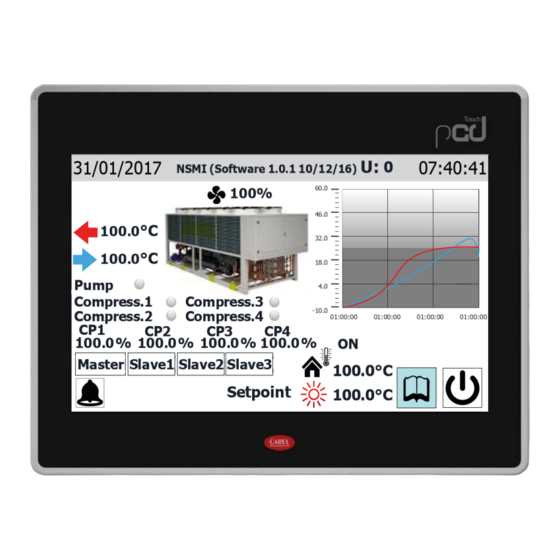
11. Percentage data on the power supplied by compressor 3
12. Percentage data on the power supplied by compressor 4
13. This key selects the Master compressor as data source (this selection is only
available on the Master unit)
14. This key selects the Slave 1 compressor as data source (this selection is only
available on the Master unit)
15. This key selects the Slave 2 compressor as data source (this selection is only
available on the Master unit)
16. This key selects the Slave 3 compressor as data source (this selection is only
available on the Master unit)
ATTENTION: via serial (pLAN connection), the pCO5 control board can
manage up to 4 compressors, which are identified as:
U1: Master;
U2: Slave 1;
U3: Slave 2;
U4: Slave 3;
THE MAXIMU NUMBER OF UNITS THAT CAN BE CONNECTED VIA SERIAL
(pLAN) DEPENDS ON THE NUMBER OF COMPRESSORS THAT THE UNIT
HAS. In fact, if the system contains only one bi-compressor unit, the in-
terface will show as available the Master data (U:1) and the Slave 1 data
(U:2); similarly, the same case might indicate that the system is com-
posed of two separate single-compressor units.
8
3.4 DATA ENTERED IN THE LOWER BAR, AND NAVIGATION
KEYS
5
1. Current unit status; the possible displays on the unit are:
On = Unit functioning;
Off from alarm = Unit switched off due to the arising of an alarm condition;
OFF via supervisor = Unit switched off via BMS;
Off from range = Unit switched off because required by currently active time period;
Off from dig.inp. = Unit switched off by signal on digital input (ID1);
Off from keyboard = Unit switched off through key (6);
Pumpdown = Unit currently engaged in pumpdown cycle;
2. Value of the outside air temperature (real time value)
3. This icon indicates the current set-point being used (summer or winter) on the
basis of the selected operating mode
4. Indicates the current value for the operating set-point
5. This icon is displayed if there is an active alarm on the system - press it to view
the alarm menu
6. Press this key to visualise the menu selection page
7. Press this key to switch the unit ON or OFF directly
Note: If the system uses a MASTER/SLAVE configuration, remember that up to two
units can be managed with a "pLAN" serial connection (the address of the C-touch
MASTER panel must be "3", and that of the SLAVE "4"). It is recommended that the
two units - Master and Slave - are the same (same software version), so they can be
used in a balanced manner.
WARNING: it is essential that the Master and Slave units have the same
software version.
2
1
3
4
6
7
