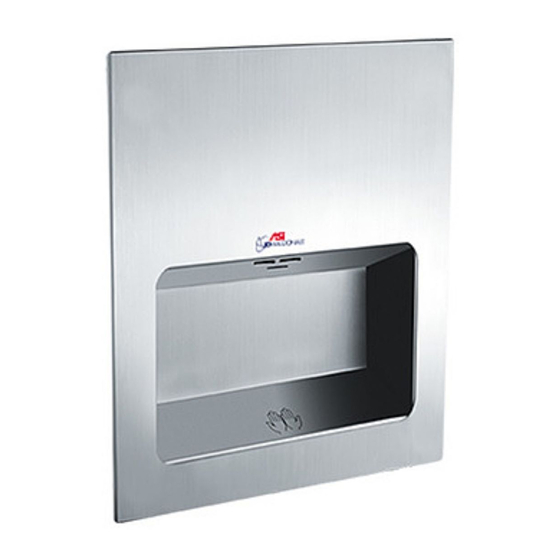
ASI JD MACDONALD Turbo-Tuff 10-0135-2 Mode d'emploi et manuel des pièces détachées - Page 2
Parcourez en ligne ou téléchargez le pdf Mode d'emploi et manuel des pièces détachées pour {nom_de_la_catégorie} ASI JD MACDONALD Turbo-Tuff 10-0135-2. ASI JD MACDONALD Turbo-Tuff 10-0135-2 8 pages. Recessed high-speed ada-compliant hand dryer

Hand Dryer
Input
Model
VAC
№
Vac
220
0135-2
220
230
0135-2
230
240
0135-2
240
Installation
1. Make sure power supply breaker is switched off. Installation must be carried out in accordance with the
current edition of the local wiring regulations code having jurisdiction. Installation should be performed
only by a qualified electrician.
2. Remove front panel using security wrench included in kit and retain security screws. Place cover aside with
care to protect face finish until required in step 8.
3. Remove hand drying chamber using #2 PhilIips screwdriver and retain screws. Place chamber aside with
care to protect inside finish until required in step 7.
4. Remove two (2) mounting screws from bottom edge of chassis plate using #2 PhilIips screwdriver and retain
screws. Grasp motor securely and lift entire chassis slightly up & over retainer hooks welded to housing
top. Place chassis aside with care to protect unit until required in step 5.
5. Install supplied plastic KO bushing (or other, not supplied) into KO to be used for cable prior to installation
of cable into KO or box into RWO (Rough Wall Opening, previously prepared by others). Install wall box
housing into RWO locating stub cable into any one (1) of five (5) available KO locations on sides or top
of box. Using screws supplied with unit (or other types suitable to wall conditions, by others) tighten screws
through adjustable mounting tabs into framing in side walls of RWO to center wall box in opening.
6. Grasp chassis & motor assembly retained in step 3 and slightly lift to place over retainer hooks on housing
top to hold unit in place while driving screws. Using #2 PhilIips screwdriver tighten two (2) screws also
retained in step 3 through holes in bottom edge of chassis plate into threaded posts on wall box back.
7. Refer to Circuit Diagram on page 4 of this Owner's Manual to match correct wire to terminal block on motor
chassis. Pull stub cable through bushing (previously installed, step 4) to allow clearance around hand drying
chamber (to be installed next) and enough length to prep ends for terminal block insertion after routing through
strain relief clamp on chassis. Clamp cable, prep ends of wires and insert correct wires into terminal block
at locations L, N & G. Using a small flat blade screwdriver ensure each wire is properly secured with terminal
block top lock screws.
Connections: (see fig. 6 & refer to Circuit Diagram and see Note B)
A. Connect the live wire (colored Brown, Red or Black) to the terminal block marked "L".
B. Connect the neutral wire (colored Black, Blue, White or Grey) or connect the second live wire (colored
Red or Orange) to the terminal block marked "N".
C. Connect the ground wire to the terminal block marked "
grounding (earth) wires should be sleeved with green and yellow or green tubing.
Colors of live and neutral wires depend on voltage of supply service and requirements of Building and
Electrical Code having jurisdiction.
8. Reinstall hand drying chamber retained in step 2 into wall box housing using #2 PhilIips screw driver and
screws also retained in step 2 while being careful to not pinch cable arranged to route clear around hand
chamber in step 6.
9. Fasten the front panel onto the chassis box using the two (2) security screws retained in step 1 above
using the security wrench. Retain wrench for any possible service access during dryer lifetime. Turn ON
breaker at service panel (by others) and test dryer operation.
10. Record the unit S/N on the Registration Card and give this Owner's Manual, the Installation Guide, Registration
Post Card and the security wrench to Owner or Facility Manager .
Operating Instructions and Parts Manual
ADA
Recessed High-Speed
Motor
Inrush A(W)
Operating A(W)
2.86 (630)
1.91 (420)
2.99 (689)
2.00 (459)
3.13 (750)
2.08 (500)
-compliant hand dryer
Heater
Operating A(W)
Vac
220
1.91 (420)
230
2.00 (459)
240
2.08 (500)
" or to the green screw marked "
2
A S I J D M a c D o n a l d P t y . L t d .
www.asijdmacdonald.com.au
1800 023 441
Total
Inrush A(W)
Operating A(W)
4.77 (1050)
3.82 (840)
4.99 (1148)
3.99 (918)
5.21 (1250)
4.17 (1000)
". Bare
www.asijdmacdonald.com.au
