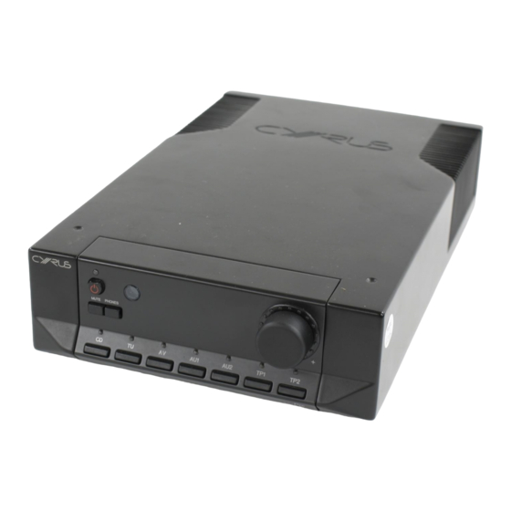
Cyrus aCA7.5 Instructions pour l'utilisateur - Page 4
Parcourez en ligne ou téléchargez le pdf Instructions pour l'utilisateur pour {nom_de_la_catégorie} Cyrus aCA7.5. Cyrus aCA7.5 6 pages.

Cyrus Pre aCA7.5
Welcome to the world of Cyrus!
Congratulations on your choice of Cyrus Hi-fi products. Our state-of-the-art
design technology and outstanding quality of manufacture has won countless
awards around the world. We are confident that you will derive great pleasure
from owning a product from one of the most recognised and respected
manufacturers of hi-fi equipment.
Please read these instructions carefully before commencing installation. They
provide full guidance to help you install your Pre aCA7.5 safely and correctly.
Preparations for Installation
Before installing the Pre aCA7.5 check that the following items are included in
the accessory box.
•
Warranty Card (with instruction manual)
•
Power Cable
•
Remote Handset
•
2 MC-Bus cables
After removing these items, please retain the packaging.
Install the Pre aCA7.5 in a well ventilated location away from sources of high
temperature, dust or humidity. Never stand the Pre aCA7.5 under another unit
or on any surface likely to obstruct its cooling or ventilation.
INSTALLATION
(Refer to Fig 1):
Key to the rear panel drawing:
1. Headphone Output
2. MC-Bus System Connection
3. Pre-Amplifier Output 2
4. Pre-Amplifier Output 1
5. Tape Recorder Output 2
6. Tape Recorder Output 1
7. Tape 2 Input
8. Tape 1 Input
9. Aux 2 Input
Connecting to the AC Mains Supply
Connect the socket on the AC Power cable to the Power inlet 1% on the rear panel
of the Pre aCA7.5. Now connect the cable to a suitable AC power point.
Connecting a Power Amplifier
Connect a phono cable from the Pre-amplifier 1 Output sockets d to the input
of your power amplifier. The additional Preamplifier 2 Output is provided to
feed twin power amplifiers for bi-amping.
If the power amplifier is located a long way from the Pre aCA7.5, the
Balanced outputs 1& are recommended. In this case connect suitable
Balanced connection cables between the Pre aCA7.5 and a suitable balanced
input of the power amplifier.
Connecting Signal Inputs
Connect a phono cable between each component and the sockets as marked
on the rear panel. Ensure left and right channels are correctly connected. The
Pre aCA7.5 has inputs for CD Player -CD 1#, a tuner - TU 1@, a Home Theatre
decoder - AV 1! and two auxiliary inputs – AU1 1) and AU2 i which can be
used to connect a wide variety of products. Check the specification of these
products before connecting to your Pre aCA7.5.
Connecting a Turntable
The Pre aCA7.5 is a line level amplifier. To play a turntable through your unit
an external phono pre-amplifier is required.
2
10. Aux 1 Input
11. AV Input
12. Tuner Input
13. CD Input
14. PSX-R Connection
15. Power Inlet
16. Mains Fuse Holder
17. Balanced Outputs
Connecting Tape/Disc recorders
A tape recorder may be connected to the Pre aCA7.5 in two ways- if a full
tape monitor circuit is required (for three-head cassette decks etc) connect
the tape recorder to TP2. If tape monitor is not required connection to the TP1
input is recommended.
To connect the tape recorder you will need two phono cables. Connect one
cable from the Output or Playback sockets of the tape deck to the appropriate
Tape Input – TP1 IN h or TP2 IN g of the Pre aCA7.5 and a second cable
from the Input or Record sockets of the tape deck to the Tape Record Output
sockets of the Pre aCA7.5.
NOTE:- If the main system tape recorder is connected to TP2, a second tape
recorder may additionally be connected to TP1. This facility enables tape
copies to be made from TP1 to TP2.
Connecting Headphones
The headphones socket a is a standard 6.35mm (¼") stereo jack socket for
connection to a pair of headphones. Headphones may be permanently
connected to the amplifier and selected when required with the front panel
switch.
MC-BUS System
(Refer to figs 1 & 7)
Connecting the MC-BUS sockets b of the Pre aCA7.5 in an MC-BUS system
provides unified system control. An MC-BUS loop is established by
connecting single phono cables from the MC-BUS output of one unit to the
MC-BUS input of another in a daisy-chain. Complete the loop by returning the
MC-BUS output of the final component to the MC-BUS input of the first.
With MC-BUS established you can control the power function of the entire
system from the Pre aCA7.5, from the front panel or remote control. Selecting
'CD' from the front panel will switch on the Pre aCA7.5, the Cyrus Power and
a Cyrus CD player. When the Pre aCA7.5 is set to Standby, the entire system
will also switch off.
When a Cyrus Surround Processor is in the MC-BUS loop, setting of the
volume calibration level will take place automatically when Pre aCA7.5's AV
input is selected. Refer to the handbook for AV-master or AV5 for further
details.
External Regulated Power Supply - PSX-R
The PSX-R is a unique DC power supply which will upgrade the sonic
performance of your Pre aCA7.5 and enhance its current drive. When a Pre
aCA7.5 / PSX-R combination is installed, analogue and signal related
sections of the Pre aCA7.5 are powered from this clean, stable power source
while other requirements are supplied internally. This ensures complete
isolation of control circuits and sensitive analogue sections reducing AC
mains-borne noise and power supply ripple.
To connect the PSX-R to the Pre aCA7.5 plug the connector on the umbilical
cord of the PSX-R into the Multi-Pole socket on the rear of the Pre aCA7.5 (1$
Fig.1) You will need a mains supply for both units.
User Instructions
GB
GB
