ambiq micro Apollo3 Blue Plus Manuel de démarrage rapide - Page 7
Parcourez en ligne ou téléchargez le pdf Manuel de démarrage rapide pour {nom_de_la_catégorie} ambiq micro Apollo3 Blue Plus. ambiq micro Apollo3 Blue Plus 15 pages.

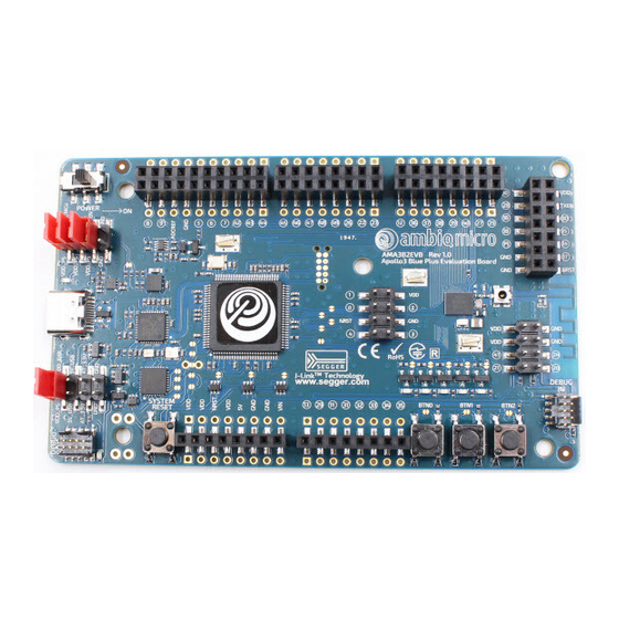
The EVB has these additional features:
▪ Low power reference design
▪ Apollo3 Blue Plus MCU in the BGA package (AMA3B2KK-KBR)
▪ Multiple power/clock options
▪ Micro USB Type C connector for power/download/debug
▪ On-board PCB (MIFA) antenna
▪ FTDI USB-to-SPI adapter/interface
▪ RF switch/connector (J1 - Murata MM8430-2610RA1) for BLE PHY testing
▪ Segger J-Link debugger
▪ Debugger-in port
▪ Debugger-out port with connection-indication LED
▪ Five user-controlled LEDs
▪ Three push buttons for application use, plus a reset push button
▪ Power slide switch with LED power indicator
▪ Five 8-12 pin Arduino-style headers for pin/power access to shield board(s)
▪ Multiple test points for power measurements
▪ CE Mark and RoHS compliant
Caution: The EVB has components loaded on the back of the board. Care should be taken to not damage
these components. Rubber feet have been applied to the bottom of the board to prevent direct contact
between the components and a desk surface.
3.1
Secure Boot on the Apollo3 Blue Plus MCU
Apollo3 Blue Plus MCU parts from the Ambiq Micro factory are preprogrammed with a Secure Bootloader
and an uninitialized Customer InfoSpace, referred to as INFO0. Initial provisioning of the part would include
programming a valid INFO0 and programming the main firmware image in the flash. The Apollo3 Blue Plus
EVB is shipped with the INFO0 configuration preprogrammed with optimal settings for the EVB layout.
For your reference, the following settings are programmed into INFO0 on the Apollo3 Blue Plus MCU
resident on the EVB:
▪ Simo Buck is enabled, which provides lowest Apollo3 Plus power consumption in both active and sleep
modes.
▪ Secure Bootloader (SBL) interface is configured to UART using GPIO22 and GPIO23, which allows
secure boot to be performed over the J-Link COM interface of the EVB.
▪ SBL override pin is configured to GPIO16 which is BTN1 on the EVB.
▪ All Flash and Debugger protection features are disabled.
For information on changing the INFO0 settings as well as using the Secure Bootloader, please refer to the
Apollo3 Blue Getting Started Guide, which can be found in the Ambiq Micro SDK documentation and
example scripts located in the \tools\apollo3_blue_scripts folder. This folder contains a number of python
scripts to demonstrate generation of INFO0 settings, customer main images, and the creation of images
for the Wired Update protocol over UART.
QS_A3P_1p1
Apollo3 Blue Plus EVB Quick Start Guide
Ultra-Low Power Apollo MCU Family
Page 7
2020 Ambiq Micro, Inc.
All rights reserved.
