AMCI SMD23-240 Panduan Pengguna - Halaman 8
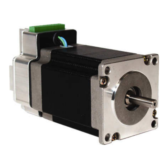
Jelajahi secara online atau unduh pdf Panduan Pengguna untuk Unit Kontrol AMCI SMD23-240. AMCI SMD23-240 14 halaman. Integrated stepper drive & motor

ADV ANC ED
MIC RO CON T RO L S INC.
SMD23 Electrical Installation
Control Signal Wiring
Programmer Wiring – CSMD-5 cable
SMD Connector – AMCI part # MS-8P
To SMD
1. DC Supply
2. DC Common
3. DTR
4. RXD
5. RTS
6. N/C
7. TXD
8. GND
Use a general purpose diode with a breakdown voltage greater than 30Vdc such as 1N4005
or 1N4148 to protect the SMD RTS input.
The eight pin connector of the SMD is used for programming and control. The SMD drive monitors
the TXD signal coming from the computer's serial port for a specific sequence of data. When the
SMD receives this data, it enters programming mode. To exit programming mode you must cycle
power on the SMD and reconnect the motion control signals. The SMD automatically enters motion
mode when power is re-applied.
20 Gear Drive, Plymouth Industrial Park, Terryville, CT 06786
Tel: (860) 585-1254
Fax: (860) 584-1973
Power supply inputs are NOT reverse connection protected. Applying
reverse voltage will damage unit.
Logic inputs are rated for 5Vdc max. Exceeding 5vdc will damage the
unit unless the recommended limiting resistors are used.
Pin 1 +Vdc
Pin 2 Vdc Common
Pin 3 – Disable
Pin 4 + Disable
–
–
–
+
+
+
V
V
D
D
S
S
IN
IN
IS
IS
TP
TP
1 2 3 4 5 6 7 8
24-75Vdc
Vdc com
Web: www.amci.com
SMD-23 Integrated Stepper Drive & Motor
Pin 5 – Step
Pin 6 + Step
Pin 7 – Direction
Pin 8 + Direction
–
+
D
D
IR
IR
0.43" Nominal
(10.9 Nominal)
Serial Port Connector – DB-9
To PC Serial Port
1. N/C
2. RXD
3. TXD
4. DTR
5. GND
6. N/C
7. RTS
8. N/C
9. N/C
page: 8
