AMD Geode GX DB533 Panduan Pengguna - Halaman 4
Jelajahi secara online atau unduh pdf Panduan Pengguna untuk Motherboard AMD Geode GX DB533. AMD Geode GX DB533 6 halaman. Development board

3.0
System Architecture
The CPU module board is offered with either a CRT inter-
face (-TC) or a TFT interface (-TT). The base board is
equipped to handle either interface.
128 MB DDR
SDRAM
Clock
Generator
Battery
USB Host x4
IDE
AC97 v2.1
PS2, SER
AMD Geode Device
Component
Connector
*This processor operates at 400 MHz. Model numbers reflect performance as described here:
http://www.amd.com/connectivitysolutions/geodegxbenchmark.
4
AMD Geode™
Processor*
AMD Geode™
CS5535
Companion
Device
Figure 3-1. CPU Module Board Block Diagram
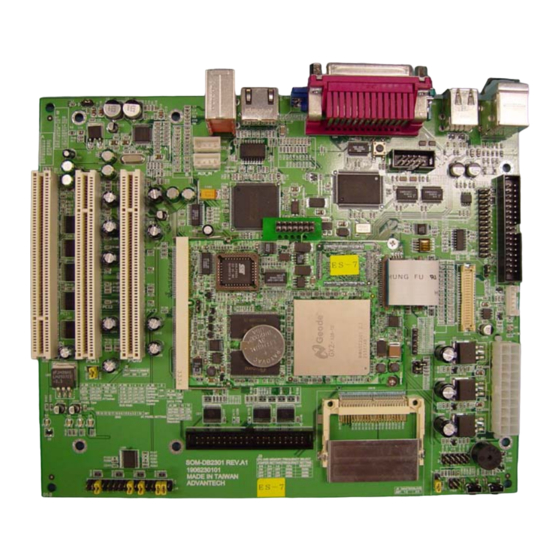
Figure 3-1 is a block diagram of the CPU module board
showing both the CRT and TFT interfaces. Figure 3-2 on
page 5 provides a block diagram of the base board and
illustrates how it connects with the CPU module board.
V
CORE
V
MEM
V
TT
V
IO
V
IO_VSB
Analog RGB (-TC only)
40-Pin Connector
(-TT only)
10/100
Ethernet
(not installed)
Power Control
BIOS
LPC SIO
(not installed)
AMD Geode™ GX DB533 Development Board Overview
Overview
31538A - May 2004 - Confidential
Power
Supplies
SMB
LPC
