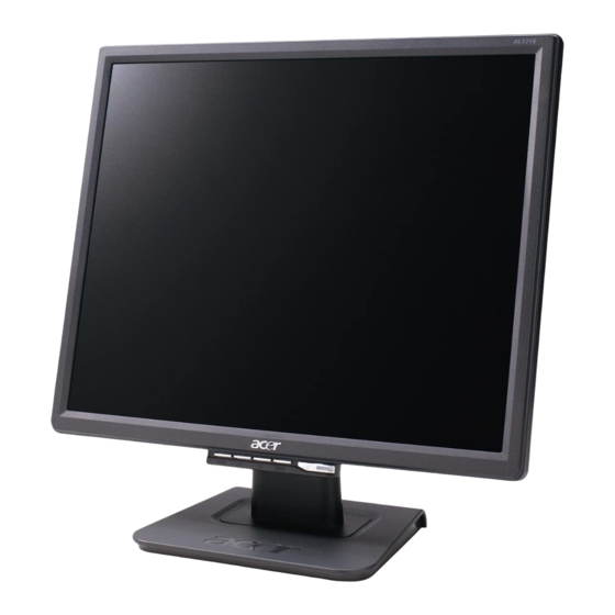
Acer AL1716W Panduan Servis - Halaman 3
Jelajahi secara online atau unduh pdf Panduan Servis untuk Monitor Acer AL1716W. Acer AL1716W 50 halaman. Acer computer monitor user guide
Juga untuk Acer AL1716W: Panduan Pengguna (17 halaman)

ACER AL1716W
2
Go to cover page
1.1 Scope:
This document defines the design and performance
requirements for the Liteon standard 17" wide flat
panel monitor. The display element shall be a 17" inch
diagonal, WXGA (1440 x 900) resolution, TFT-LCD
(Thin Film Transistor Liquid Crystal Display). Video
input signals are Analog D-sub with non-interlaced
signaling. Power saving function complies with the
DPMS (Display Power Management Standard).
1.1.1 General display parameters
Display Area
17" diagonal,367.2(H)x229.5(V)
Resolution
1440 x 900 pixels
Display Color Number
16.2M colors
Display Type
a-Si TFT active-matrix
Contrast Ratio
500 : 1 typ.
Brightness
250cd/m
Response Time
(Ton + Toff) 8 ms typ.
Pixel Pitch
0.255mm x 0.255mm RGB Vertical Stripes
Vertical Viewing
130 degrees typ,
CR>10
Horizontal Viewing
140 degrees typ,
CR>10
1.1.2 Optical Characteristics
The panel model name is HSD170MGW1-A
supplied by Hannstar.
1.2 General Requirements:
1.2.1 Test Condition
Brightness level at max & contrast level at default
full white pattern test mode following spec. Warm
up more than 30min, ambient light < 1 Lux,
Luminance meter CA210 or BM7 or compatible
equipment.
1.2.2 Test Equipment
The reference signal source is a calibrated
Chroma 2326 or Quantum 801GD video
generator. The use of other signal generators
during qualification and production is acceptable
provided the product complies with this
specification.
1. Product Specification
2
typ.
1.2.3 Electrical
This section describes the electrical requirement of
the monitor. The block diagram in Figure 1 illustrates
the various electrical sub–system.
5V
Function Key Board
Regulator
5V ~ 3.3V
5V ~ 1.8V
R.G.B & Hs, Vs
Analog Video
The LCD monitor will contain an interface board, a
Power/Inverter board, and a function key board. The
interface block will house the flat panel control logic,
brightness control logic, and DC-DC conversion to
supply the appropriate power to the whole board and
LCD panel, and transmitting LVDS signals into LCD
Module to drive the LCD display circuit. The inverter
block will drive the two CCFLs (Cold Cathode
fluorescent Tube). The power block will provide the
DC power to interface board and LCD panel. The
function key block will provides the OSD control
signal, power ON/OFF and LED indicator to the
interface board.
ITEM
Frequency Ranges
Max Pixel clock
Analog Signal Input
RGB Input Level
RGB Input Impedance
Sync Input Signal
Sync Input Impedance
AC power
Connectors
Input connectors
AC IN 90~264V
Normal Operation
Power Consumption
Standby, Suspend,
Active Off
Power Off
User's Control
Front Panel Buttons
Dimming control range
(max-min/max) x 100%
Pre-Defined Timing
Plug and Play
Power Saving
Input Signal Counter tolerance
LCD Panel
Inverter Output
+5V & DIM & Enable
+5V Vcc
LVDS
DIM & Enable
SST25VF01
Scaler IC
GM5726H
XTAL
EEPROM
14.318MHz
24CL16
EEPROM
24C02
D-SUB
Input
SPEC
H 31kHz ~ 83kHz
V 56Hz ~ 76Hz
205MHz
0.7Vp-p
75Ω
Separate SYNC, Composite Sync
50Ω
AC 100V ~ AC 220V ± 10% 50/60Hz, 3 pin
AC power cord
D-SUB 15 pin
35W Max
< 2W
< 1W @ (90VAC~240VAC)
POWER, MENU, SELECT, + , -
35% typical
18
VESA DDC2B
DPMS
H ±1kHz, V ±1 Hz
Power & Inverter
AC 110/220V
Input
