Aktek TRFM 1.0 Panduan Pengguna - Halaman 9
Jelajahi secara online atau unduh pdf Panduan Pengguna untuk Alat Ukur Aktek TRFM 1.0. Aktek TRFM 1.0 18 halaman. Turbine flowmeter

www.aktek.com.tr
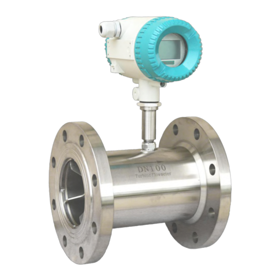
Ball bearing 2.Front guide part 3.Expansion ring 4.Casing 5.Preamplifier
6.Impeller 7.Bearing
8.Shaft
Fig. 5 Wiring diagram for connection between sensor and display instrument
II. Installation Requirements
Flow meter may be installed horizontally or vertically. In the latter case the fluid shall
be flowing from downward and fulfill the pipe to avoid bubbles; the flowing direction
of liquid shall be consistent with the direction indicated by the arrow on casing of the
sensor; as far as front and rear straight pipe sections are concerned (see Fig. 6), at
upstream there shall be front straight pipe section at least 10 times of nominal drift
diameter in length and at downstream no less than 5 times of nominal drift diameter in
length. The internal wall of pipe sections shall be smooth and clean, free of defects
such as indent, fouling and peeling. The pipe axis of the sensor shall be aligned with
that of the neighboring pipe and the washers used for connection and sealing may not
be embedded into depth of the pipe cavity; the sensors shall be kept away from
foreign electric field and magnetic field, effective shielding measures shall be taken in
case of necessity to avoid external interference.
7
AKTEK Endüstriyel Ekipman ve Enstrümantasyon LTD.ŞTİ.
İMES Sanayi Sitesi B-Blok 204.Sok. No:40 Y.Dudullu-Ümraniye/İSTANBUL
