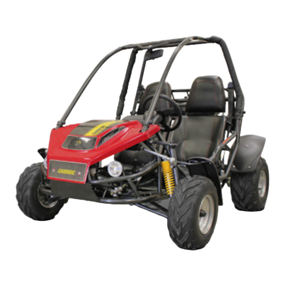
American Sportworks 7151 Panduan Pemilik / Panduan Suku Cadang - Halaman 12
Jelajahi secara online atau unduh pdf Panduan Pemilik / Panduan Suku Cadang untuk Kendaraan Utilitas American Sportworks 7151. American Sportworks 7151 13 halaman. Ages 13+ / 39 mph max speed 150cc fun kart

maintenance
A. Front Wheel Replacement
Do not disassemble the castle nuts when you replace the front wheels. It is only
necessary to remove the 4 lug nuts to remove the wheel. (See Figure)
Tighten the nuts securely after replacing the wheels.
B. Rear Wheel Replacement
Do not disassemble the castle nuts when you replace the rear wheels. It is only
necessary to remove the 4 lug nuts to remove the wheel. (See Figure)
Tighten the nuts after replacing the wheels.
C. Front Wheel Alignment
The front wheels should be set with a "toe-in" from 1/8" to 1/4". At the centerline of the tires,
measure the Distance A and the Distance B. For proper toe adjustment, Dimension A should
be 1/8" – 1/4" greater than Dimension B.
To make adjustments:
a. Loosen the lock nuts on both sides of Front Tie Rods.
b. Ensure the steering wheel is centered, and adjust Dimension B by equally rotating the
tie rods in or out with a 12mm wrench.
c. After adjusting to the desired length, tighten the lock nut against the rod end.
d. Recheck the dimensions for proper alignment.
D. Optional Speed Reduction Installation
This kart has been equipped with provision for a speed limiter to reduce the overall speed
of the unit to 20mph max. This kit is available from your dealer or directly from American
SportWorks by calling customer service.
To install the speed limiter:
a. Remove the electrical control box cover located on the rear swing arm, just next to
the air box, using a Phillips screwdriver.
b. Locate the CDI (black box with 2 wire plugs)
c. Unplug the old CDI and replace with the new Rev Limited CDI provided in the kit.
d. Replace the electrical box cover, being careful not to damage or crush any wires
and connections.
NOTE: Keep the original CDI so that the kart can be changed back
to the original factory setting if desired.
fig. D1
15516R1
GENERAL MAINTENANCE
(see fig. A1)
(see fig. A1)
(see fig. C1)
7151 OWNERS MANUAL / ILLUSTRATED PARTS LIST
SECTION 4
(see fig. D1)
CL
CAUTION
!
Prevailing torque type locknuts must be replaced with
new after the old locknuts are removed.
fig. A1
A
B
fig. C1
Toe Adjustment Diagram
WHEEL TIE ROD
CL
8
