Barnes SGV3042L Manual Instalasi - Halaman 6
Jelajahi secara online atau unduh pdf Manual Instalasi untuk Pompa Air Barnes SGV3042L. Barnes SGV3042L 18 halaman. Submersible grinder pump 3, 5, 7.5hp, 3450rpm
RECEIVING/UNPACKING:
Upon receiving the pump, it should be inspected for dam-
age or shortages. If damage has occurred, fi le a claim
immediately with the company that delivered the pump.
Unpack pump and record pump serial and model number
before installing. If the manual is removed from the pack-
aging, do not lose or misplace.
STORAGE:
Short Term- For best results, pumps can be retained in
storage, as factory assembled, in a dry atmosphere with
constant temperatures for up to six (6) months.
Long Term- Any length of time exceeding six (6) months,
but not more than twenty-four (24) months. The units
should be stored in a temperature controlled area, a roofed
over walled enclosure that provides protection from the
elements (rain, snow, wind-blown dust, etc.), and whose
temperature can be maintained between +40 deg. F and
+120 deg. F. If extended high humidity is expected to be
a problem, all exposed parts should be inspected before
storage and all surfaces that have the paint scratched,
damaged, or worn should be recoated with a air dry
enamel paint. All surfaces should then be sprayed with a
rust-inhibiting oil.
Pump should be stored in its original shipping container.
On initial start up, rotate shaft by hand to assure seal
and motor rotate freely. If it is required that the pump be
installed and tested before the long term storage begins,
such installation will be allowed provided:
1.)
The pump is not installed under water for more than
one (1) month.
2.)
Immediately upon satisfactory completion of the
test, the pump is removed, thoroughly dried,
repacked in the original shipping container, and
placed in a temperature controlled storage area.
SERVICE CENTERS:
For the location of the nearest Barnes Service Center, check
your Barnes representative or Crane Pumps & Systems, Inc.,
Service Department in Piqua, Ohio, telephone (937) 778-8947
or in Brampton, Ontario, Canada (905) 457-6223.
INSTALLATION:
Location - The pump is designed to fi t into your basin either
by sliding down the rail assembly, suspended from the
cover or by being mounted on a pump base. THIS PUMP
MUST BE INSTALLED WITH A MINIMUM OF 3 INCHES
AND A MAXIMUM OF 4.5 INCHES OF CLEARANCE
UNDER THE PUMP FOR THE ENTRANCE OF SEWAGE
SOLIDS.
MENU
HOME
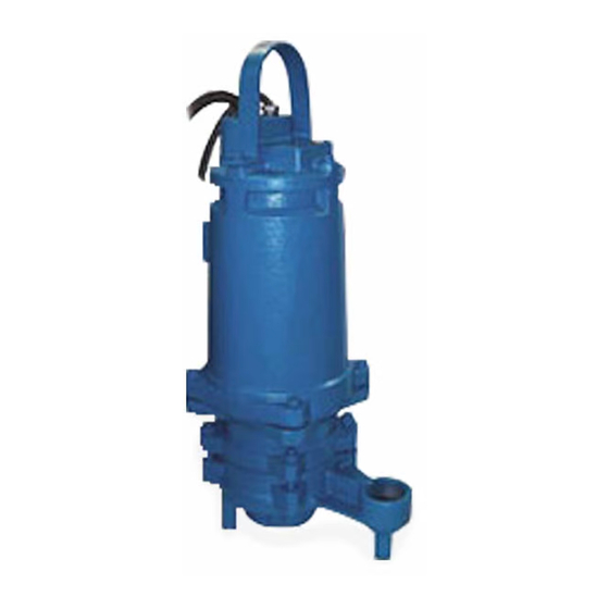
FIGURE 1 - L Series
Discharge - Assemble discharge piping or hose assembly
(whichever is required by your application), to the pump. Dis-
charge piping should be as short as possible. Both a check
valve and a shut-off valve are required for each pump being
used. The check valve is used to prevent backfl ow into the
sump. Excessive backfl ow can cause fl ooding and/or dam-
age to the pump. The shut-off valve is used to stop system
fl ow during pump or check valve servicing.
Package Systems- Refer to manual supplied with basin
package system.
ELECTRICAL CONNECTIONS:
Pump Cords - The quick connect cord assembly mounted
to the pump must NOT be modifi ed in any way except for
shortening to a specifi c application. Any supply cable con-
nections between the pump and the control panel must be
made in accordance with the National Electric Code or the
Canadian Electric Code and all applicable state, province
and local electric codes. It is recommended that a junction
box, be mounted outside the sump or be of at least Nema
4 (EEMAC-4) construction if located within the wet well.
DO NOT USE THE POWER OR CONTROL CABLES TO
LIFT PUMP!
Thermal Protection - The normally closed (N/C) over
temperature sensor is embedded in the motor windings
and will detect excessive heat in the event an overload
condition occurs. The thermal sensor will trip when the
windings become too hot and will automatically reset
itself when the pump motor cools to a safe temperature.
It is recommended that the thermal sensor be connected
in series to an alarm device to alert the operator of an
overtemperature condition and/or motor starter coil to stop
pump.
6
Manual Index