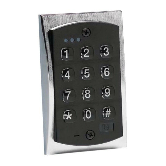
Door-Gard 2000e Instalasi & Pemrograman - Halaman 7
Jelajahi secara online atau unduh pdf Instalasi & Pemrograman untuk Papan tombol Door-Gard 2000e. Door-Gard 2000e 7 halaman.

2000e & 2000eM Keypad Installation & Programming
Wiring the 2000-8EX Output Module
If the Output Module is within 18 inches of the keypad, use the
6-conductor wire harness, supplied with the Output Module, to make
the connection.
If your Output Module is located more than 18 inches from the keypad
(up to a maximum of 100 feet), you must cut the wire harness in half
and plug one half into the keypad the other into the Output Module.
Then connect the two using 22 AWG stranded and shielded cable.
Make sure you connect the wire harness pin to pin (pin 1 on the
Output Module to pin 1 on the keypad and so on). You must connect
the drain wire from your cable to the negative on your keypad (the
black wire to your power supply).
Performing the Programming Mode Loopback
The keypad has a special loopback connection you can make to enter
program mode if you do not know the master code. Use the following
steps below and refer to the diagram.
Note: This procedure should only be performed by a qualifi ed security
or lock industry professional.
1.
Power down the keypad.
2.
Connect the white/yellow, brown and white wires together and
disconnect any other connections to these wires.
3.
Power up the keypad.
4.
Change the master code or default the keypad
5.
Power down the keypad and remove the loopback connections
and reconnect any other wiring to these wires.
6.
Power up the keypad.
6-104402 X2
Performing the Keypad Self-Test
After installing the keypad, it is recommended that you perform the
keypad self-test once a year to ensure that the keypad is working
properly.
1.
To perform the self-test, with the unit powered up, press the
following keys on the keypad: 7890 # 123456 ✱
2.
If all 12 key presses are accepted, the keypad enters self-test
mode.
3.
The LEDs then turn on one at time with a beep in the following
order Red, Yellow then Green.
4.
After the Green LED, the unit then fl ashes an LED to indicate
which operating mode the keypad is programmed mode. Below
shows which LED fl ashes for each mode:
● Standalone Mode: Red Flash
● Wiegand Front End Mode: Green Flash
● Secured Series Front End Mode: Yellow Flash followed by
rapid yellow fl icker.
Note: If the unit is not connected to a controller in
Secured Series Front End Mode, the yellow LED
turns on solid after the yellow fl ash. Press the ✱
key to clear.
Limited Warranty
This Nortek Security & Control product is warranted against defects in
material and workmanship for twenty four (24) months. This warranty
extends only to wholesale customers who buy direct from Nortek
Security & Control or through Nortek Security & Control's normal
distribution channels. Nortek Security & Control does not warrant
this product to consumers. Consumers should inquire from their
selling dealer as to the nature of the dealer's warranty, if any. There
are no obligations or liabilities on the part of Nortek Security
& Control LLC for consequential damages arising out of or in
connection with use or performance of this product or other
indirect damages with respect to loss of property, revenue, or
profi t, or cost of removal, installation, or reinstallation. All implied
warranties, including implied warranties for merchantability and
implied warranties for fi tness, are valid only until the warranty expires.
This Nortek Security & Control LLC Warranty is in lieu of all other
warranties express or implied.
All products returned for warranty service require a Return
Authorization Number (RA#). Contact Returns at 1-855-546-3351 for
an RA# and other important details.
Technical Support
DEALERS/INSTALLERS ONLY! End users must contact
the dealer/installer for support. If the keypad still does
not work after troubleshooting, please call the Technical
Services department at 1-800-421-1587.
7
