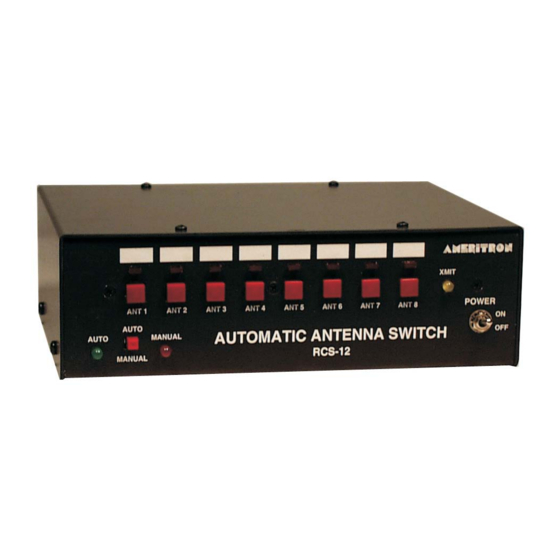
AMERITRON RCS-12 Buku Petunjuk - Halaman 6
Jelajahi secara online atau unduh pdf Buku Petunjuk untuk Beralih AMERITRON RCS-12. AMERITRON RCS-12 16 halaman. Automatic antenna switch

Ameritron RCS-12 Instruction Manual
Installation
Powering the RCS-12
The RCS-12 accepts 2.5x5.5mm coaxial jack for power with a input voltage ranging from +12V to +30V
DC. The input voltage is also used to provide the switching voltage needed for the Relay Box. The input
voltage must be at least the voltage needed to control the Relay Box. If the relay's require +30VDC, then
the input voltage into the RCS-12 must be +30VDC.
Connecting the RCS-12 to the Tower- Mounted Relay Box
Locate the Relay Output jack on the rear left of the RCS-12. This 8-pin DIN jack provides the voltage to
switch the relays in the tower-mounted switching box. The RCS-12 was designed to work with the
RCS10/12 Relay Box and many other off the shelf relay boxes.
Using the RCS-12 with the RCS-10 Relay Box
The RCS-10 Relay Box operates on 3-line BCD data; therefore, including ground, it requires a 4
conductor cable to connect it to the RCS-12. This cable should be fitted with an 8-pin DIN plug on the
RCS-12 side and end-stripped on the relay box end so that it may be attached to the terminal strip on the
RCS-10 (see the diagrams below and the RCS-10 manual). The RCS-12 may also be used with the RCS-
8V if only 5 antennas are need with automatic selection, refer to the RCS-8V manual.
NOTE: Ground is connected to the outer shell of the 8-pin din plug. Failure to connect
ground to the outer shell will result in the relay box not operating correctly.
Using the RCS-12 with other brand relay boxes
The RCS-12 was designed to be compatible with most off the shelf relay boxes. The RCS-12 Control
Head will work with any relay boxes using 3-line BCD, 4-line BCD, or 1 of 8 output; and require 12 – 30
VDC to switch the relays. The output format of the RCS-12 (BCD or 1 of 8) is changed by configuring
J9, J10, and J11 on the PCB (see diagram below to configure the RCS-12). Position the jumper on the
desired block to select the correct output needed for the relay box.
To connect the antenna switch to the relay box, the connections must be wired according to the output
chosen. The following diagram shows the connections to the relay jack for each mode of output. Ground
is provided using the outer shell of the plug.
Wiring Pin Out and Relay Jack (Rear View)
Pin 1 – BCD A
Pin 2 – BCD B
Pin 3 – BCD C
4
Automatic Antenna Switch
