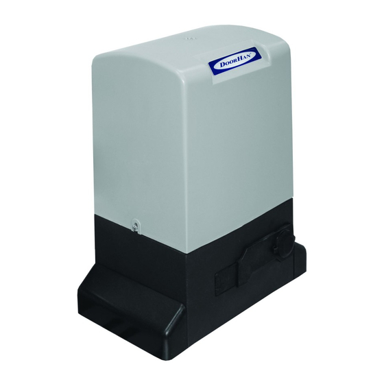
DoorHan SLIDING-1300 Panduan Instalasi dan Pengoperasian - Halaman 7
Jelajahi secara online atau unduh pdf Panduan Instalasi dan Pengoperasian untuk Pembuka Gerbang DoorHan SLIDING-1300. DoorHan SLIDING-1300 12 halaman. Drive
Juga untuk DoorHan SLIDING-1300: Panduan Instalasi dan Pengoperasian (16 halaman), Panduan Instalasi dan Pengoperasian (12 halaman)

Rack Installation on the DoorHan gate
1.
Installed C-profile (3) in door leaf brackets (4) and fixed it by self-tepping screw.
2.
Installed bolt with plate (1) into C-profile.
3.
In top of C-profile installed fixing element (5)so that the bolt (1) was in the hole of fixing element.
4.
twist plug (2) on a bolt, but do not pull it. the plug (2) should press the fixing element (5) to C-profile (3).
5.
In front of the hole in the rack installed element that we made in 4 operation.
6.
repeat (2-5) operations for other fixing elements. their quantity should coincide with total holes quantity in the rack.
7.
Fix rack on fixing elements with bolts (6).
8.
using free rack, level teeth all section elements.
9.
pull all fixing elements.
10.
Move the gate manually and be convinced, that during movement all rack elements do not leave from operator
pinion.
11.
do not weld rack to plugs or to each other.
12.
to provide correct gearing rack with operator pinion, establish distance between operator pinion and rack~2 mm.
13.
Check up, that a gate reached mechanical stops and that during gate movement there was not any frictions.
14.
do not grease neither rack, nor operator pinion.
11. Adjustment the limit switch
an operator slIdIng-1300 (2100) is equipped magnetic contacts which react on moving of the magnet
installed on rack, also a command on a stop of gate.
Installed trailer magnets in the following sequence:
1.unblock a drive (look "emergency manual release lever").
2.Manually move gate to open position, having left 2-5 sm to a mechanical stops.
3.Move a magnet of opening limit switch along rack in a direction of opening of gate to that time while
limit switch unit will not pass in mode oFF. to know it you should look to led on the control board, (look
«Check of parameters of work of system»). Move a magnet in the same direction still approximately on 20-30
mm also fix it on rack.
4.Move gate to the closed position, having left 2-5 sm to a mechanical stops.
5.Move a magnet of closing limit switch along rack in a direction of closing of gate to that time while limit
switch unit will not pass in mode oFF. to know it you should look to led on the control board, (look «Check
of parametres of work of system»). Move a magnet in the same direction still approximately on 20-30 mm
also fix it on rack.
6.Move gate to average position and block an operator (look. ""emergency manual release lever").
7.limit switches devide on: the closing limit switch on the long support, the switch opening limit switch
on a short support. If you change limit switches the normal work of a drive is not possible.
8.to provide normal work of system, leave 2 sm from gate to a mechanical stops in extreme opened and
extreme closed positions of gate.
9.do some full work cycles and check up limit switches installation. When operator stoped on limit switch
the right led should switch off. sw1 -closing limit switch. sw2 - opening limit switch.
10.the distance from the limit switch to a magnet limit switch should be no more than 5 mm.
12. Emergency manual release lever.
If it is necessary to open the gate manually in disconnected electricity or malfunctions of an operator, use
emergency manual release lever:
1. Insert a key into the lock. (Fig. 1)
2. turn a key to clockwise.
3. Without taking out a key, pull the emergency manual release lever to itself ( Fig. 2).
4.turn a key counter-clockwise and take out a key from the lock.
5.Move gate manually.
Returning to normal system action.
to prevent an involuntary push at activation of gate, disconnect electricity before an operator blocking.
1. Insert a key into the lock.
2. turn a key counter-clockwise.
3. Without taking out a key close the emergency manual release lever from itself against the stop.
4. turn a key to clockwise and take out a key from the lock.
5. Move gate manually until the operator will not be blocked
6.do not grease neither rack, nor operator pinion.
7
I n s t a l l a t I o n a n d o p e r a t I n g M a n u a l o p e r a t o r s l I d I n g - 1 3 0 0 / 2 1 0 0
RACk InstALLAtIon on tHe DooRHAn GAte
4
3
6
2
5
2
6
1
5
Closing limit swith
Opening limit switch
7
