Dormakaba 5750-K Manual Instalasi - Halaman 4
Jelajahi secara online atau unduh pdf Manual Instalasi untuk Sistem interkom Dormakaba 5750-K. Dormakaba 5750-K 9 halaman. Electronic entry device
Juga untuk Dormakaba 5750-K: Petunjuk Pengoperasian Pengguna (2 halaman), Petunjuk Pengoperasian Pengguna (2 halaman)
dormakaba
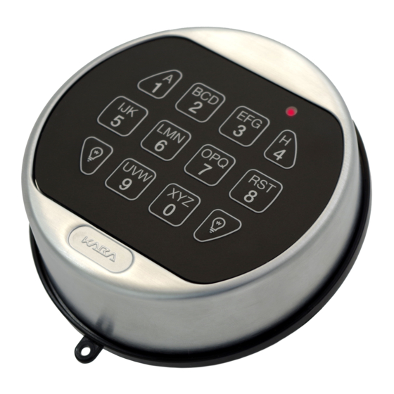
The 3000 and 5715 Entry Devices are designed with keyhole slots for
ease of mounting and battery replacement.
1. Install the two #8-32 shoulder screws (US) or the M4-0.7 shoulder
screws (metric) to mount the Entry Device to the door.
2. Feed the key pad cable through the spindle cable hole from the
front of the safe door. Leave approximately 2 inches (50mm) of the
cable extended out the front of the container door, to allow for
battery replacement.
3. Position the Entry Device over the mounting screws and then slide
the Entry Device down onto the mounting screws. (Figures 1 & 2)
4. Ensure that the Entry Device cable is running through the channel
at the back of the lock.
Figure 1
INSTALLING BATTERIES
1. Slide the keypad housing up and carefully pull away from mounting
surface to expose battery compartment.
CAUTION! Hold onto the battery connector to avoid pulling the wires
out of the board.
2. Connect a new 9-Volt alkaline battery to the battery connector.
3. Push the battery and the leads completely into the battery
compartment.
4. Repeat procedure for second battery ( 3000 only).
5. Carefully position the keypad over the mounting screws and slide
the keypad housing down. Ensure there are no wires or cables
trapped between the Entry Device and the safe door.
NOTE: The 3125 entry is not UL listed.
SWING BOLT
1. Mount the dial plate (p/n 2676) centered on the through hole. Attach the dial plate with
the two mounting screws US 8-32 (US) or the M4-0.7 (metric), and the shoulder
bushings (p/n 2618).
2. Slide the bearing plate (p/n 2674) over cable and press onto the fasteners on the Entry
Device.
3. Feed the key pad cable through the spindle cable hole from the front of the safe door.
4. Insert the springs (p/n 2893) and blocking pins (p/n 2894) into the hole located on the
back of the key pad.
5. Rotate the key pad approx. 30° counter-clockwise and place onto the bushings. Then
turn the key pad clockwise until the blocking pin clicks, and secures the Entry Device to
the safe door.
WARNING: Once installed, the Entry Device cannot be removed from the safe door without
causing physical damage to the Entry Device.
6. When installing the lock, ensure that the Entry Device cable is running through the channel
at the back of the lock.
(P/N) 762.128 Rev G 05/17 • © copyright 2009-2018
3000 AND 5715 ROUND ENTRY DEVICES
Figure 2
3035 AND 3125 ROUND ENTRY DEVICES
3000
Keyhole Slots
3000
3125
3035 & 3125 Entry Device
(Swing Bolt Option)
1. Key Pad
2. Bearing Plate
3. Mounting Screws
4. Shoulder Bushing
5715
Keyhole Slots
9 Volt
Battery
5715
5. Dial Plate
6. Spring
7. Blocking Pin
3