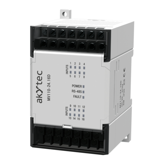
Akytec MV110-16DN Panduan Pengguna - Halaman 8
Jelajahi secara online atau unduh pdf Panduan Pengguna untuk Unit Kontrol Akytec MV110-16DN. Akytec MV110-16DN 19 halaman. Analog input module, 16 channel

Installation
–
PNP transistor outputs
When connecting the following is to observe:
The inputs of the module MV110-16DN are galvanically isolated in groups of 4 (1...4,
5...8, 9...12, 13...16). When connecting the sensors, use only to the group related com-
mon negative terminal, please:
–
inputs DI1...DI4
–
inputs DI5...DI8
–
inputs DI9...DI12
–
inputs DI13...D16 – terminal SS4
Table 4.1 Terminal assignment of MV110-16DN
No
1
2
3
4
5
6
7
8
9
10
11
12
Connection variants for different signal types are shown in Figures 4.2 – 4.4.
akYtec GmbH · Vahrenwalder Str. 269 A · 30179 Hannover · Germany · Tel.: +49 (0) 511 16 59 672-0 · www.akytec.de
– terminal SS1
– terminal SS2
– terminal SS3
Fig. 4.1 Electrical connections of MV110-16DN
Connection
Description
0 V
Power supply
24 V
Power supply
DI1
DI1
DI2
DI2
DI3
DI3
DI4
DI4
SS1
Input voltage 1-4
DI5
DI5
DI6
DI6
DI7
DI7
DI8
DI8
SS2
Input voltage 5-8
No
Connection
13
D-
14
D+
15
DI9
16
DI10
17
DI11
18
DI12
19
SS3
Input voltage 9-12
20
DI13
21
DI14
22
DI15
23
DI16
24
SS4
Input voltage 13-16
Description
RS485 D-
RS485 D+
DI9
DI10
DI11
DI12
DI13
DI14
DI15
DI16
7
