Akytec ITP11-G Panduan Pengguna - Halaman 6
Jelajahi secara online atau unduh pdf Panduan Pengguna untuk Alat Ukur Akytec ITP11-G. Akytec ITP11-G 15 halaman. Process indicator 4-20 ma

Functional description
4
Functional description
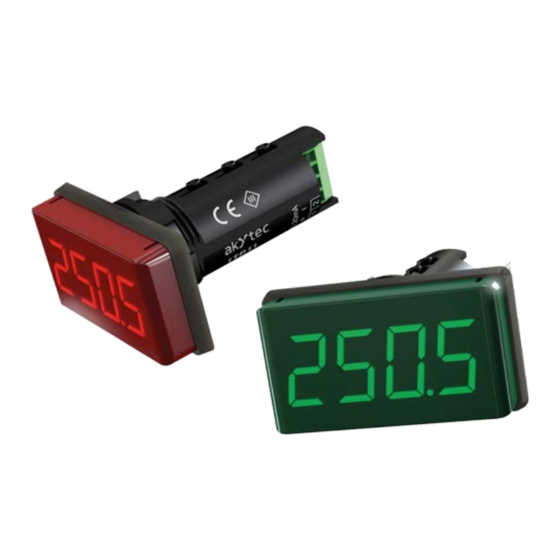
A 4-digit, 7-segment LED display with 14 mm character height is located on the front of
the device for displaying the measured values, error messages, functions and values
during programming. The programming buttons are positioned on the cylindrical surface
of the device.
The
rameters can be selected and changed using buttons
the buttons increases the speed of parameter changing in three steps.
The operating modes are described in Section 5.
The device has the following functions:
−
−
−
−
−
−
4-20 mА
akYtec GmbH · Vahrenwalder Str. 269 A · 30179 Hannover· Germany · Tel.: +49 (0) 511 16 59 672-0 · www.akytec.de
button is used to set the programming mode and to apply the changes. The pa-
Display process values, received from process control devices with 4-20 mA out-
put (current loop).
The measured values are displayed on the 4-digit LED display with a maximum
range of -999...+9999 in accordance with the set limit values and the decimal
point position.
When exceeding the measuring limit, the device displays an error message.
Switching between linear and square root function (for special transmitters)
Filter for damping the signal fluctuations with an adjustable time constant
Protection against unauthorized access
ITP11
A/D
Digital filter
Fig. 4.1 Block diagram
and
. Pressing and holding
Microcontroller
Square
Scaling and
root
adjusting
function
5
