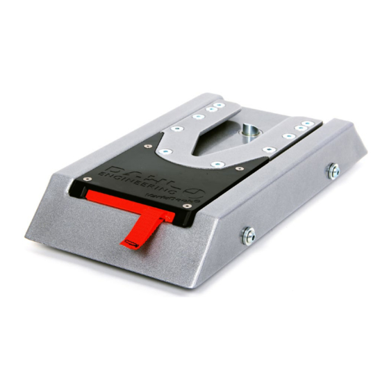
Dahl VARIODOCK Panduan Pemeliharaan - Halaman 12
Jelajahi secara online atau unduh pdf Panduan Pemeliharaan untuk Stasiun Docking Dahl VARIODOCK. Dahl VARIODOCK 19 halaman.

Electrical connection
1.
Disconnect the cable on the battery's negative terminal.
2.
Find a suitable installation site for the control panel.
If the docking station is used by a person driving the vehicle himself
– At an easily accessible and visible location when the wheelchair is
secured in the docking station and the driver is looking forward from
the driving position.
If the docking station is for a passenger – At a location which is visible
when the driver of the vehicle is sitting in the driver's seat and looking
forward.
3.
Wiring must be installed so that it is not exposed to mechanical loads
such as wear, vibrations, kinks and sharp edges which can cause breaks
and result in malfunctions or, in the worst case, a short circuit.
To ensure sufficient power supply to the docking station, the supply
cable must be installed directly to the vehicle's battery, otherwise there
is a risk of malfunction and overload of the vehicle's original wiring.
The power supply must be fused with a 30 amp fuse (not included.) See
the wiring diagram on page 24 for correct connection.
4.
Electrical connection
- To reset the maintenance counter, press the reset button down on the
circuit board for approx. 15 seconds. The yellow LED on the control
panel flashes when the reset is done.
- Parking brake (1) and (2): Polarity is not important.
- The software reset is performed by pressing the up and down buttons
of the control panel simultaneously for 3 seconds.
- Function when lock pin is blocked: To protect the electrical system
from overload, the power supply for the locking mechanism will
pulsate if blocking the lock pin. This can be can be heard as pulsating/
clicking sound from inside the docking station.
22
Maintenance manual, installation and user guide UK
Settings on DIP switches
DIP 1 og DIP 2:
Setting the tightening rate by pressing the blue button on the control panel
If VarioDock is to be used for multiple wheelchairs, we recommend choosing a low
tightening rate to avoid any damage to the wheelchairs due to excessive pulling.
! NOTE: Please enquire from the wheelchair manufacturer whether the wheelchair
may be pulled down, in order to avoid damage to the wheelchair.
DIP 1
DIP 2
Tightening rate
OFF
OFF
15 kg +/- 10
OFF
ON
30 kg +/- 10
ON
OFF
40 kg +/- 10
ON
ON
50 kg +/- 10
DIP 3: Holding time of the lock pin
DIP 3
Holding time of the lock pin
OFF
5 seconds
ON
8 seconds
DIP 4: Activation of parking brake
DIP 4
Parking brake contact function: NO or NC
OFF
If a signal is connected when the parking brake is being activated, so that
12V can be measured on the control unit's parking brake terminals 1 and
2 (polarity is irrelevant), switch 4 on DIP switch must be set to OFF (NO
function).
ON
If a signal is cut off when the parking brake is activated, so that 12 V
CANNOT be measured on the control module's parking brake terminals 1
and 2 (polarity is irrelevant), switch 4 on DIP switch must be set to ON (NC
function).
DIP 5: Display which shows ground clearance (see Fig. I on page 15) can be set
to be permanently active or switch off after 30 seconds.
DIP 5
Display state
OFF
Display will switch off after 30 seconds
ON
Display is permanently active
DIP 6: No function
DIP 7 og DIP 8: Calibration of the height
Prior to calibration, it must be ensured that VarioDock can be adjusted with-
in the full range of travel (61-91mm)! Settings MUST be made in the order
shown.
DIP 7
DIP 8
Function
OFF
OFF
1.
Adjust VarioDock™ to approx. middle of the full range
of travel
ON
OFF
2.
Adjust the VarioDock™ to the top position – wait until
it stops by itself, before releasing the button
ON
OFF
3.
Adjust the VarioDock™ to the bottom position - wait
until it stops by itself, before releasing the button
ON
ON
4.
Set the display to lowest position in millimetres
(61mm) with the up / down buttons
ON
OFF
5.
Adjust the VarioDock™ to the top position - wait until
it stops by itself, before releasing the button
ON
ON
6.
Set the display to highest position in millimetres
(91mm) with the up / down buttons
OFF
OFF
7.
The settings are complete
5.
Carefully fit the docking station's top. It is important that the potentiometer
pin be placed in the hole in the bottom frame when assembling slides and
bottom frames. Otherwise there is a risk of damaging the potentiometer. If the
docking station's top is fitted and the potentionmeter is not sitting properly in
the hole, it will be damaged. See instructions on page 17. Please be careful to
place wires and cables so that they do not touch the moving parts.
6.
Fit the cable onto the battery's negative terminal.
Solenoid /
Parking
2
Electromagnet (+)
1
brake
Solenoid /
Reset-button
Electromagnet (-)
Display
+12V battery
-battery
DIP switch
Dahl VarioDock™
23
