List of contents
List of contents
1 About this document...................................................................................................................................
1.1
Purpose ..............................................................................................................................................
1.2
Warnings in this manual .....................................................................................................................
1.3
Labels in this manual ..........................................................................................................................
1.4
Disclaimer ...........................................................................................................................................
1.5
Scope of delivery ................................................................................................................................
1.6
Name plate .........................................................................................................................................
1.7
1.8
Approvals and warranty ......................................................................................................................
1.9
2 General information ....................................................................................................................................
3 Transport and storage ................................................................................................................................
3.1
Transport ............................................................................................................................................
3.2
Delivery inspection..............................................................................................................................
3.3
Storage ...............................................................................................................................................
4 Description...................................................................................................................................................
4.1
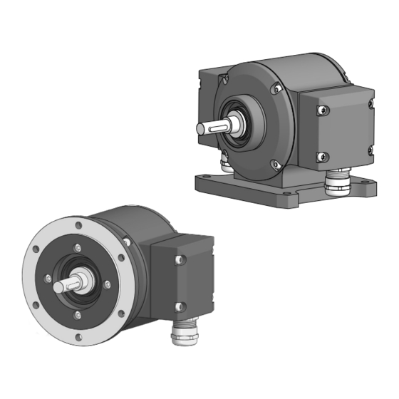
Rotary encoder ...................................................................................................................................
4.2
4.3
Required tools..................................................................................................................................... 10
5 Installation.................................................................................................................................................... 11
5.1
5.1.1
5.1.2
5.2
Mounting with base B3 ....................................................................................................................... 15
5.2.1
5.2.2
5.3
washer ................................................................................................................................................
5.4
6 Electrical installation................................................................................................................................... 20
6.1
DeviceNet ........................................................................................................................................... 21
6.1.1
DeviceNet features ............................................................................................................... 21
6.1.2
6.1.3
Pin assignment DeviceNet .................................................................................................... 24
6.1.3.1
6.1.3.2
6.1.4
DeviceNet terminal box ......................................................................................................... 26
6.1.5
6.1.6
6.1.7
ii
Operating Manual
Baumer Hübner
PMG10 & PMG10P DeviceNet | V1
4
4
4
4
4
5
5
6
6
6
7
8
8
8
8
9
9
18