Baumer 11185990 Panduan Memulai Cepat - Halaman 2
Jelajahi secara online atau unduh pdf Panduan Memulai Cepat untuk Kamera Digital Baumer 11185990. Baumer 11185990 2 halaman.
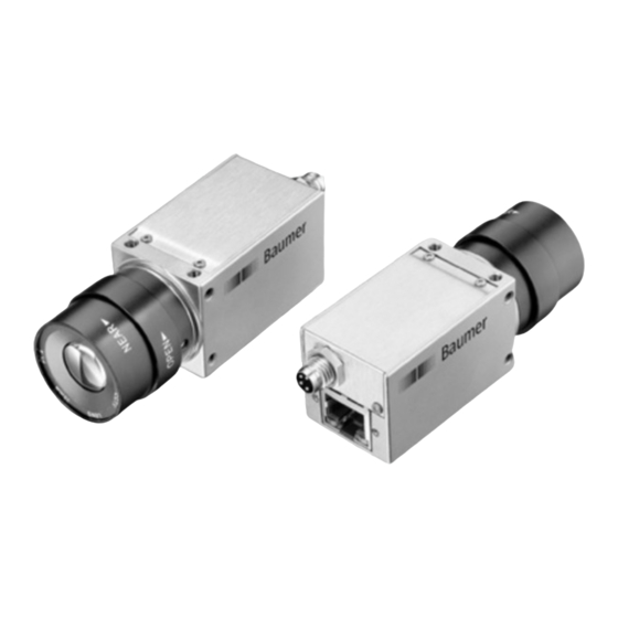
General Description
1
3
No.
Description
No.
Description
1
Lens mount (C-mount)
3
Ethernet Port / Signaling LED's
Power supply /
2
Digital-IO
Data Interface / Digital IOs
8P8C mod jack with LEDs
8
1
1
green/white
MX1+
(negative / positive V
2
green
MX1-
(negative / positive V
3
orange/white
MX2+
(positive / negative V
4
blue
MX3+
5
blue/white
MX3-
6
orange
MX2-
(positive / negative V
7
brown/white
MX4+
8
brown
MX4-
Power Supply / Digital-IOs (on camera side)
wire colors on connecting cable (ordered separately)
3
4
2
1
1
Power VCC
brown
3
GND
2
IN1 (Line0)
white
4
OUT1 (Line1)
LED signals
2
LED
Signal
green static
1
green flash
yellow static
2
yellow flash
Power Supply
Power Supply
)
port
)
port
)
port
)
port
blue
black
1
2
Meaning
link active
receiving
error
transmitting
Power Supply
VCC: 12 ... 24 VDC ± 20%
Heat Transmission
Caution
Heat can damage the camera. Heat must be dissipated adequately
to ensure that the temperature does not exceed the values in the
table below.
As there are numerous possibilities for installation, Baumer recom-
mends no specific method for proper heat dissipation, but suggest the
following principles:
▪ operate the cameras only in mounted condition
▪ mounting in combination with forced convection may provide proper
heat dissipation
T
Measurement Point
Maximum Temperature
65 °C (149 °F)
Measurement Point (T)
VEXG-100 / VEXG-52: 60 °C (140 °F)
Installation
Installation of the camera:
▪ Connect the camera using an appropriate cable (at least Cat-5e) to the GigE
board on your PC.
▪ If required, connect a trigger and / or flash to process interface.
▪ Connect the camera to power supply.
open wire
Installation sample
1 - PCI board
2 - GigE cable
3 - Power cable / Digital-IO