Dover Blackmer TLGLF3C Petunjuk Pemasangan, Pengoperasian, dan Pemeliharaan - Halaman 3
Jelajahi secara online atau unduh pdf Petunjuk Pemasangan, Pengoperasian, dan Pemeliharaan untuk Pompa Air Dover Blackmer TLGLF3C. Dover Blackmer TLGLF3C 12 halaman. Liquefied gas pumps

NOTICE:
Blackmer pumps must only be installed in systems
designed by qualified engineering personnel.
design must conform with all applicable regulations and
codes and provide warning of all system hazards.
NOTICE:
This pump shall be installed in accordance with the
requirements of NFPA 58, all applicable local, state and
national regulations.
WELDED CONNECTIONS
NOTICE:
Pumps with welded connections contain non-metallic o-
ring seals that will be damaged if welding is done with
these o-rings installed.
Prior to welding the piping, remove the O-rings from under the
auxiliary inlet flange, outlet flange and relief valve cover.
Reinstall the flanges. Weld the piping to the auxiliary inlet
flange and outlet flanges. After the welding is complete,
reinstall the O-rings.
PUMP MOUNTING
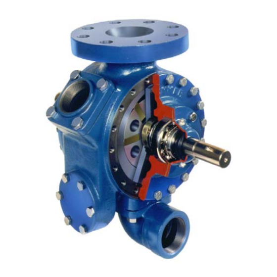
TLGLF3C pumps are designed to flange mount directly to a
commercial internal control valve in combination with the tank
of a bobtail truck or transport.
PRE-INSTALLATION CLEANING
NOTICE:
New pumps contain residual test fluid and rust inhibitor.
If necessary, flush pump prior to use.
Foreign matter entering the pump WILL cause extensive
damage. The supply tank and intake piping MUST be
cleaned and flushed prior to pump installation and operation.
INSTALLATION
LOCATION AND PIPING
Pump life and performance will be significantly reduced when
System
installed in an improperly designed system. Before starting
the layout and installation of the piping system, review the
following:
1. When locating the pump on the tank, safety should be the
first consideration. Other considerations include the
length of drive line, accessibility for maintenance and
convenience of connections. See Figure 3.
2. The discharge hose and fittings should be large enough to
minimize the pressure drop in the system. The lower the
friction loss, the higher the flow rate.
3.
ALL piping and fittings MUST be properly supported to
prevent any piping loads from being placed on the pump.
4. Check alignment of pipes to pump to avoid strains which
might later cause misalignment. See Figure 2. Unbolt
flanges or break union joints. Pipes should not spring
away or drop down. After pump has been in operation for
a week or two, completely recheck alignment.
5. Install pressure gauges in the NPT ports provided in the
pump casing to check pump performance at start up.
6. The use of a 1.5" or 2" vapor return line will speed up
delivery by preventing pressure build up at the receiving
tank and reducing pressure in the supply tank.
7. Keeping the liquefied gas systems full of liquid, even when
idle, will keep the O-rings from changing shape, shrinking
or super cooling. Evaporation of liquefied gas leaves an
abrasive powder on the surface which can cause wear to
the pump, meter, and seals.
AUXILIARY INLET
The auxiliary inlet port can be used as a fill connection for
bottom loading of the tank by stationary pumps at the terminal
or bulk plant. It can also be used as an auxiliary pump inlet,
allowing the pump to unload another tank in an emergency.
To minimize vapor formation, the auxiliary intake line must be
as large in diameter as the intake connection and as short as
possible. The line must be connected through a suitable
strainer using a minimum 40 mesh strainer screen. Reduce
pump speed to a maximum of 400 RPM when using the
auxiliary inlet. This will reduce cavitation.
501-D00
Page 3/12
Figure 2
