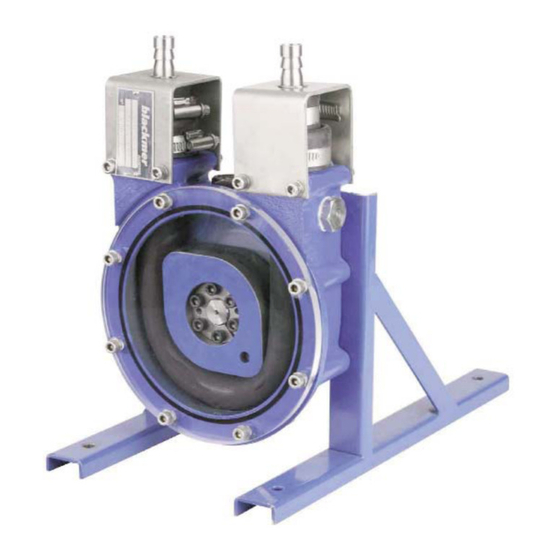
Dover MOUVEX AS10 Petunjuk Manual - Halaman 12
Jelajahi secara online atau unduh pdf Petunjuk Manual untuk Pompa Air Dover MOUVEX AS10. Dover MOUVEX AS10 16 halaman.

4. MAINTENANCE OPERATIONS (continued)
FILLING WITH LUBRICANT :
CAUTION
THE PUMP LUBRICANT IS VERY SLIPPERY
AND MAY CAUSE SERIOUS INJURY. ANY
SPILLS MUST BE CLEANED UP.
Slippery lubricant.
Spills should be
cleaned up.
Loosen plug 11 and plug 23 located at the top of th body.
Fill the pump body with lubricant (see § LUBRICATION).
Tighten plugs 11 and 23 in the body.
Handle the lubricant with care.
Wear suitable clothes and protect yourself from pump
lubricant spatters.
Run the pump for a few minutes to check correct operation.
Reinstall the inlet and discharge piping.
Put the leak detection kit back in place, if the pump is
equipped with one.
In the event that the breathing vent has been removed,
check the installation direction for the existing back flow valve
(the valve must allow air out and block it from entering).
4.2 Re-assembling and disassembling the
wheel
Disassembly and reassembly of the wheel 3 are required
when :
- Replacing the shaft seal 26.
- Performing a complete overhaul.
- Disassembling or replacing the bearing box or the
reduction gear.
For disassemble the wheel 3, the pump hose must be
removed (see § REPLACING THE HOSE).
NT 1101-A00 09.11 A10 - AS10 e
NOTES
4.2.1 DISASSEMBLING THE WHEEL
Loosen screws 19a in the hub 19.
Tighten one of the screws 19a into the tapped hole of the
hub 19 provided to pull out the cone.
Remove the wheel 3 by sliding it along the central axis.
4.2.2 ASSEMBLING THE WHEEL
Check the shaft seal 26. Replace when necessary,
making sure that it is assembled so that the spring can
be seen inside the pump body.
Check that the wheel have no dents or deep scratches
that may quickly dereriorate the hose.
Insert the parts of the hub 19 in the wheel center.
Screws 19a must not be tightened so the wheel
assembly can freely slide along the axis.
The flat side of the wheel 3 must be positioned on the
front side of the pump as well as the screws 19a of
the expansible hub.
Slide wheel 3 with its hub 19 on the axis.
Align wheel 3 with pump body 1 while keeping setting
distance as indicated on the following diagram :
After checking that the expansible hub is properly cente-
red with regard to the wheel thickness, gradually tighten
screws 19a while keeping wheel alignment correct.
12/16
NOTES
Keying distance (L) :
39 ± 1 mm
(1,535± 0,039 in)
