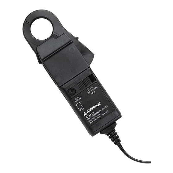
Amprobe CT237A Manual - Halaman 5
Jelajahi secara online atau unduh pdf Manual untuk Peralatan Uji Amprobe CT237A. Amprobe CT237A 9 halaman.

1.888.610.7664
Operating Instructions
Refer to Fig. 1. When the probe is switched on the red LED will illuminate. If
the LED starts flashing this warns the user that the battery voltage is too low
for normal operations and that it should be changed as described in Battery
Replacement.
Switch On
When the probe is switched on, the red LED will illuminate. If the LED starts
flashing this warns the user that the battery voltage is too low for normal
operation and that it should be changed as described in Battery Replacement.
Zero Adjustment
The output zero offset voltage of the probe may change due to thermal shifts
and other environmental conditions. To adjust the output voltage to zero
depress the thumbwheel and rotate. Ensure that the probe is away from the
current carrying conductor when the adjustment is made.
Current Measurement
Switch on the probe using the On - Off switch and check that the LED is lit.
Select the required current range (20 Amp or 200 Amp for the CT237A; 200A or
1000A for the CT235A).
Connect the output lead to a multimeter. Select AC millivolts to measure
Alternating Current and DC millivolts for Direct Current. Autoranging meters
will automatically select the correct range.
If necessary adjust the probe output voltage to zero as described in Zero
Adjustment. Clamp the jaws of the probe round the conductor ensuring a good
contact between the closing faces of the jaws.
Observe and take measurements as required. Positive output indicates that the
current flow is in the direction shown by the arrow on the probe. Multiply the
reading dependent upon the range you are in. See Output sensitivity in the
Specifications section for conversion.
True r.m.s. readings can be obtained by using an appropriate true r.m.s. reading
multimeter. Core eddy current heating is produced when Irms x f >400,000.
Safety
Use of the probe on uninsulated conductors is limited to 300V r.m.s or d.c. and
frequencies below 1kHz.
Safety in its use is the responsibility of the operator who must be a suitably
qualified or authorized person.
Do not use the probe if any part of the probe including the lead and
connector(s) appear to be damaged or if a malfunction of the instrument is
suspected.
When using the probe ensure that your fingers are behind the protective
barrier see Fig. 1
Clean the case periodically by wiping it with a damp cloth and detergent. Do
not use abrasive cleaners or solvents. Do not immerse the probe in liquids.
Battery Replacement
� Warning
Before removing the battery cover, make sure that the probe is remote from
any live electrical circuit.
The red LED will flash when the minimum operating voltage is approached.
Refer to Fig.1. and use the following procedure.
1.
Unclamp the probe from the conductor, turn it off using the On - Off
switch and disconnect the output leads from external equipment.
2.
Loosen the captive screw which secures the battery cover.
3
www.calcert.com
15
10
20
5
25
0
30
