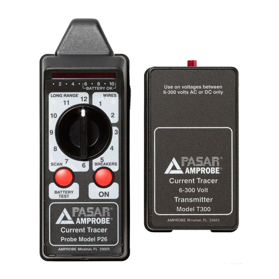
Amprobe CT-326-C Manual - Halaman 2
Jelajahi secara online atau unduh pdf Manual untuk GPS Amprobe CT-326-C. Amprobe CT-326-C 2 halaman. Current tracer
Juga untuk Amprobe CT-326-C: Panduan Pengguna (20 halaman)

Short To Ground (Fig. 5)
1. Find affected breaker panel and make sure circuit breaker is in
OFF position.
2. Attach pigtail connector to transmitter.
3. Clip one lead to shorted power line.
4. Clip the other lead to hot conductor of adjacent breaker as
shown.
5. Adjust the probe's range switch as necessary.
6. Push ON and wait for it to calibrate.
7. Hold the tip close to the shorted wire.
8. Trace the wire until the signal suddenly stops. This is the
location of the short.
Tracing Coax Cable (Fig. 6)
1. Attach pigtail connector to transmitter.
2. Clip one lead to the shield of the coax cable.
3. Clip other lead to grounded power source.
4. Follow the transmitter's signal as explained in
"Locating Wires in Walls".
NOTE: Make sure the coax shield is grounded.
Locating Ground Faults (Fig. 7)
1. Identify ground fault with voltmeter. Grounded
phase will have reduced voltage compared to the
other phases.
2. Attach pigtail connector to transmitter.
3. Clip one lead to system ground.
4. Connect the other lead to one of the two
phases that doesn't have the ground fault. The
transmitter's LED will blink if the ground fault
impedance is low enough to allow the transmitter to operate.
5. Adjust the probe's range switch as necessary.
6. Push ON and wait for the probe to calibrate.
7. Hold the probe's tip close to a faulty phase and watch for a dramatic change in LED readout.
Amprobe
®
www.Amprobe.com
Everett, WA 98203
Tel: 877-AMPROBE (267-7623)
Amprobe
®
Europe
Beha-Amprobe
In den Engematten 14,
79286 Glottertal, Germany
Tel.: +49 (0) 7684 8009 - 0
P/N 3356291 Rev 002
10/2013 6001650 A
©2013 Amprobe
Test Tools. All rights reserved.
®
Fig. 5
Fig. 6
Fig. 7
