COMECO RT284U Panduan Pengoperasian
Jelajahi secara online atau unduh pdf Panduan Pengoperasian untuk Pengontrol COMECO RT284U. COMECO RT284U 4 halaman.
Specifications
Case
Input
Outputs:
Electromechanical relay
SSR
MOS gate
Output for external SSR
- K1
- K2
Serial Interface
Power Supply
Excitation Voltage (Vaux)
Consumption
Measurement Error
Temperature Drift
RTD Line Error
Cold-junction Error
Operating Temperature / Humidity
Protection Class: front / terminals
Warranty and Support
...............................
serial number
...............................
manufacturing date
QC check mark .............(passed)
(stamp)
88 Slavyanska Str.
P.O.Box 378
Plovdiv 4000, BULGARIA
tel: +359 32 646523, 646524
fax: +359 32 634089, 646517
e-mail: [email protected]
QD-8.2.4-WC
Wiring
Important notes:
♦
Strictly observe the requirements
for RS485 network building!
♦
With DC power supply,
the polarity does not matter.
♦
In case of 90...250 VAC/DC power supply,
grounding the device via separate wire
is mandatory for covering safety standards.
'B',
'H',
'V',
'Q',
'L',
'R1',
'R2'
programmable
up to 2
5A/250VAC with NO/NC or NO contact
1A/250VAC,
0.2A/250VAC
0.1A/60V, optically isolated
5...24 VDC, 30 mA
relay,
SSR,
MOS gate,
for ext. SSR
relay,
SSR,
MOS gate,
for ext. SSR
RS485, isolated,
RS485 for "PolyMonitor", isolated
230 VAC,
90...250 VAC/DC,
24 VDC,
12...24 VAC/DC,
...................................
10...30 V, 30 mA,
........................
less than 3 VA
≤ ± 0.3% from span
≤ 0.02% from span for 1 °C
≤ ± 0.001%/Ω at R
≤ 50 Ω
lin
.
≤ ± 1 °C at air temperature -10...80 °C
-10...65 °C / 0...85% RH
IP65,
IP54 / IP20
Warranty
COMECO warrants this product
to be free from defects in materials
and workmanship for 2 years. If your unit
is found to be defective within that time,
we will promptly repair or replace it.
This warranty does not cover accidental
damage, wear or tear, or consequential
or incidental loss. This warranty
does not cover any defects caused
by wrong transportation, storage, installation,
or operating (see 'Specifications').
Technical support
In the unlikely event that you encounter
a problem with your COMECO device,
please call your local dealer or contact
directly our support team.
Input signal wiring
Connect the input
with regard to its type
through the respective and
depending on the case type
(see 'Specifications')
terminals on the device
back.
3-wire current
transmitters can be
supplied from Vaux.
Voltage transmitters must
be supplied externally!
Output wiring
Connect the outputs
with regard to their types
(see 'Specifications')
via the respective terminals.
RS485 wiring
Connect the unit
to RS485 network line
via the respective
terminals (connector).
Power supply wiring
Connect the right
power supply voltage
for your device
(see 'Specifications').
More detailed
wiring diagrams
are available at
comecogroup.com under
'Support' tab.
16
'S',
COMECO Inc., P.O.Box 378, Plovdiv 4000, BULGARIA, tel: +359 32 646523, 646524, fax: 634089
e-mail: [email protected], WWW.COMECOGROUP.COM
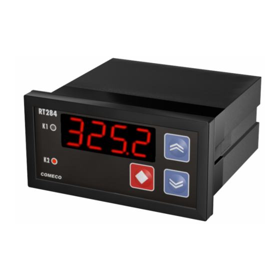
PROGRAMMABLE CONTROLLER
Please read this Operation Manual before mounting and operating!
Communication Protocol
4
Parameter Symbol
Input Type
inp
Unit
unit
Point Position
pnt
Input Low
i.hi
Input High
i.lo
Input Correction i.cor -1999...9999
Address
addr
Baud Rate
baud
Gradient
grad
Filter Time
f.t
Filter Band
f.b
Input Value
p.v
Error Info
error **
* Input Value (read-only)
numerical value with ISU - measured input value
sat.lo - ADC under-range
sat.hi - ADC over-range
inp.br - sensor break
break - device failure
noise - noisy measurement
** Error Info
0 - initializes non-volatile memory
-1 - error FAiL (read-only)
1...29 - errors ER01... ER29 (read-only)
RT284U
with keyboard
O PERA T ION MANUAL
Save the Manual for future references!
Table 2
Protocol architecture
♦
The protocol is based
Value
on UART protocol with:
pt100, pt1000,
ptc1, ptc2,
r.0.1k,
t.c.b, t.c.j,
t.c.k, t.c.r,
t.c.s, t.c.t,
♦
ASCII protocol is used
u, u.0.10,
for communicating,
i.0.20, i.4.20
and the information
is exchanged in frames.
c, f
♦
Each frame consists of 1,
0, 1, 2, 3
or 2 words separated
-1999...9999
by byte 32 (SPACE),
-1999...9999
and ends with bytes 13 (CR)
and 10 (LF). The first word
in the frame denotes
1...254
a parameter 'Symbol'
1200, 2400,
as taken from Table 2 and
4800, 9600
the second word (if needed)
0...9999
is the parameter 'Value',
both spelled with only
0...9999
small Latin letters, digits,
0...M
dots, and/or the '-' sign.
*
Device activating
♦
To respond to commands,
the device should be active.
♦
For a device to be activated,
it must receive a
command, where 'х' is
the value of the parameter
Address or the value '255' (if
device address is unknown),
and respond to it with ok..
♦
If a device does not respond
even to
the UART protocol settings,
chiefly Baud Rate value.
13
Baud Rate - as defined
by parameter Baud Rate;
Data bits - 8;
Parity Control - Even;
Stop bit - 1.
U
х
U
255, check