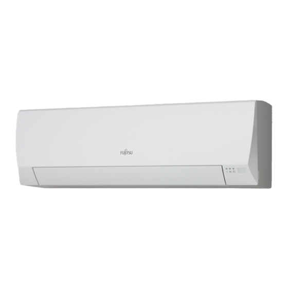
AirStage AGYA014GCAH Panduan Instalasi - Halaman 10
Jelajahi secara online atau unduh pdf Panduan Instalasi untuk Pendingin Udara AirStage AGYA014GCAH. AirStage AGYA014GCAH 15 halaman. Indoor unit (floor type)
Juga untuk AirStage AGYA014GCAH: Panduan Pengoperasian (8 halaman)

6. FINISHING
After checking for gas leaks (refer to the Installation Manual of the outdoor unit), perform
this section.
Install heat insulation around both the large (gas) and small (liquid) pipes. Failure to do
so may cause water leaks.
6.1. Connection pipe, cable and drain hose
(1) Insulate between pipes.
• Overlap the connection pipe heat insulation and indoor unit pipe heat insulation.
• Wrapping the connection pipe with cloth tape over the range within which they fit into the
rear piping housing section.
• Fasten the pipe bracket with the screw.
(2) Fill the gap between the outside wall pipe hole and the pipe with sealer so that rain
water and wind cannot blow in.
(3) Fasten the drain hose to the outside wall, etc.
Cloth
Insulation of indoor
tape
unit pipes
There
are no
gaps
Pipe
bracket
Overlap
Insulation of
refrigerant pipes
Screw
Left piping
Cable
Pipe
Drain hose
Fill the gap between the
knockout hole of the indoor
unit and the pipe or cable
with putty.
Check the following:
GOOD
Stopping
downward
End of drain hose
is immersed in
water.
Drainage
channel
7. FIELD SETTING
There are 3 methods for address setting by FIELD SETTING as follows.
Please set by either of the methods.
Each setting method is described in below (1) to (3).
(1) IU AD, REF AD SW settings: This section (7.1. Setting the address)
(2) Remote controller settings:
(3) Automatic address settings: Refer to the outdoor unit manual for detailed setting
En-9
CAUTION
Wrap the pipes
with cloth tape
There are no gaps
For connection from the left rear
Cable
Wall pipe
Drain hose
Putty
PROHIBITED
Accumulated
No upward
drain water
slope
50 mm or less
from ground
Refer to the wired or wireless remote controller manual
for detailed setting information. (Set IU AD, REF AD
SW to 0)
information. (Set IU AD, REF AD SW to 0)
7.1. Side panel L and control cover removal
Refer to "3.4. Side panel L, R removal and installation" to remove the side panel L.
7.2. Setting the address
Manual address setting method
The indoor unit address and the refrigerant circuit address can also be set up through the
wireless remote controller
Be sure to turn OFF the power before performing the field setting.
• Position and detail of the switches
Cable
• Please set it according to the following procedures when setting manually.
Right side of
pipe bracket
Use an insulated screwdriver to set the dip switches.
Be careful not to make mistakes for switch settings.
7.2.1 Indoor unit address
• Rotary switch (IU AD × 1)....Factory setting "0"
• Rotary switch (IU AD × 10)....Factory setting "0"
When connecting multiple indoor units to 1 refrigerant system, set the address at IU AD
SW as shown in the Table A
7.2.2 Refrigerant circuit address
Connection
pipe
• Rotary switch (REF AD × 1)....Factory setting "0"
• Rotary switch (REF AD × 10)....Factory setting "0"
In the case of multiple refrigerant systems, set REF AD SW as shown in the Table A for
each refrigerant system.
Set to the same refrigerant circuit address as the outdoor unit.
Setting
Indoor unit ad-
Putty
dress
Refrigerant
circuit address
Air
• If working in an environment where the wireless remote controller can be used, the ad-
dresses can also be set using the remote controller.
• If setting the addresses using the wireless remote controller, set the indoor unit address
and refrigerant circuit address to "00".
(For information on setting using the wireless remote controller.)
Table A
No
upward
Address
slope
Refrigerant circuit
0
1
2
3
4
5
6
7
8
9
10
11
12
.
.
.
99
Do no t set the indoor unit address (IU AD SW) at 64 to 99. It may result in failure .
CAUTION
For indoor unit address
For refrigerant circuit
address
CAUTION
Setting range
Type of switch
Setting
0 to 63
example 2
Setting
0 to 99
example 63
Rotary Switch Setting
Address
REF AD SW
Indoor unit
× 10
× 1
0
0
0
0
1
1
0
2
2
0
3
3
0
4
4
0
5
5
0
6
6
0
7
7
0
8
8
0
9
9
1
0
10
1
1
11
1
2
12
.
.
.
.
.
.
.
.
.
9
9
63
IU AD × 10
IU AD × 1
REF AD × 10 REF AD × 1
Rotary Switch Setting
IU AD SW
× 10
× 1
0
0
0
1
0
2
0
3
0
4
0
5
0
6
0
7
0
8
0
9
1
0
1
1
1
2
.
.
.
.
.
.
6
3
