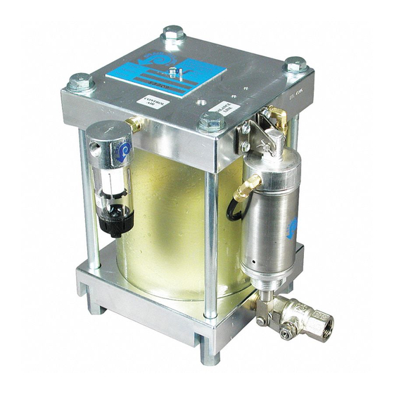
Drain-All Model 1700-IG Panduan Instalasi - Halaman 5
Jelajahi secara online atau unduh pdf Panduan Instalasi untuk Unit Kontrol Drain-All Model 1700-IG. Drain-All Model 1700-IG 12 halaman.

- 1. Table of Contents
- 2. Specifications
- 3. Installation
- 4. Start-Up & Troubleshooting
- 5. Dimensional Print
- 6. Product Technology How It Works
- 7. Component Parts Drawing
- 8. Parts & Materials of Construction
- 9. Frequently Asked Questions
- 10. Drain-All Solves Problems
- 11. Warranty
- 11. Drain-All, Inc
- 11. PO Box 609
- 11. Louisville, TN, USA
FIGURE 1: START OF CYCLE
The float (1) with a magnet molded in (2)
is sitting on the base and is at the lowest
level. The float magnet exerts a magnetic
force repelling the center tube magnet (3)
upward, holding it seated against an ori-
fice in the lower end of the valve stem
(4). This retains the control air coming in
through the control air filter (5) in the
center tube (6). The control air circuit
including the center tube magnet and
valve stem are isolated from the liquid
held in the reservoir (7). The air cylinder
(8) is in the home position and the dis-
charge ball valve (9) is closed.
There is always a residual amount of liq-
uid (10) left in the bottom of the reservoir
after each discharge cycle. The Model
1700
stops discharging before all accu-
TM
mulated liquid is removed providing a
liquid seal that conserves expensive com-
pressed air. Liquid (11) flows through the
inlet port (12) and into the reservoir to
start the fill cycle. Liquid continues to fill
the reservoir until the float has displaced
enough liquid to become buoyant and the
float pops upward to the upper position
shown in Figure 2.
022802 Model 1700-IG
PRODUCT TECHNOLOGY
HOW IT WORKS
FIGURE 2: START OF DISCHARGE
The liquid flows in and raises the float to
its highest position as shown. The float
magnet is raised up past the center tube
magnet and repels the center tube magnet
downward opening the orifice in the
valve stem. This allows the control air
held in the center tube to flow through the
control air circuit to the actuating cylin-
der. The actuating cylinder extends and
opens the ball valve starting the discharge
of accumulated liquid.
When the correct amount of liquid has
been discharged, leaving a liquid seal in
the reservoir, the float has been lowered
to a point where the float magnet is below
the center tube magnet. In this position,
the float magnet repels the center tube
magnet back upward against the valve
stem orifice, which seals off the control
air flow to the actuating cylinder. The
cylinder has a spring which then returns
the cylinder to its home position, closing
the discharge ball valve. The discharge is
stopped as shown in Figure 1 and the fill
cycle repeats.
Page 5
THE BALANCE LINE PORT
The balance line port is a hole through
the head of the Model 1700
into the reservoir. This port allows the air
trapped in the top of the reservoir to
move out of the reservoir to allow liquid
to enter the reservoir through the inlet
port. If there were no balance line port, as
liquid entered the reservoir under pres-
sure, the air trapped in the top of the
reservoir would be compressed until it
was the same pressure as the liquid com-
ing in and the unit would stop filling.
There are three methods of connecting to
the balance line port. The most effective
is to connect it back to the vessel being
drained as shown in the illustrations
above. In this configuration, the reservoir
is at the same pressure as the vessel being
drained and the liquid is filling by gravi-
ty. In this case, the top of the Model
1700
must be lower than the bottom of
TM
the vessel being drained. The balance line
can also be attached to a header pipe
leaving the vessel being drained or vent-
ed to atmosphere using a needle valve.
Venting to atmosphere uses very little air
if the needle valve is adjusted properly.
that goes
TM
