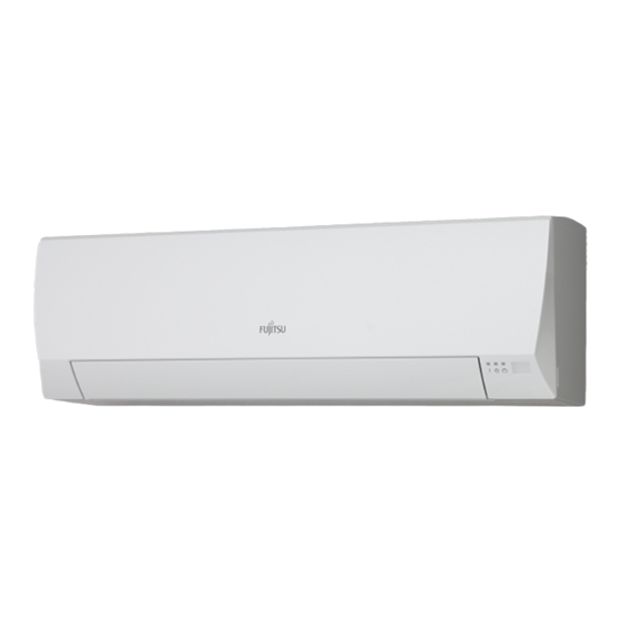
AirStage ASYA007GTAH Panduan Instalasi - Halaman 13
Jelajahi secara online atau unduh pdf Panduan Instalasi untuk Pendingin Udara AirStage ASYA007GTAH. AirStage ASYA007GTAH 15 halaman. Indoor unit (floor type)
Juga untuk AirStage ASYA007GTAH: Panduan Pengoperasian (8 halaman)

Operation behavior
Connector
External output 1
Pins 1-2
External output 2
CNB01
Pins 1-3
External output 3
Pins 1-4
6.4.3 Connection methods
Wire modification
(1) Remove insulation from wire attached to wire kit connector.
(2) Remove insulation from field supplied cable. Use crimp type insulated butt connector
to join field cable and wire kit wire.
(3) Connect the wire with connecting wire with solder.
IMPORTANT:
Be sure to insulate the connection between the wires.
Locally purchased
Solder and insulate the connected parts.
Connection terminals and wiring arrangement
In following figure, all the possible connectors are connected for description.
In actual installation, you cannot connect all the connectors at once.
004/007/009 model
CNA02
CNA01
CNA03
Controller
PCB
030/034 model
Controller PCB
Output voltage
Status
0V
Stop
DC 12 V
Operation
0V
Normal
DC 12 V
Error
0V
Indoor unit fan stop
DC 12 V
Indoor unit fan operation
Option parts:
External input /output wire
CNA04
CNB01
Connecting
cables
CNB01
CNA04
CNA03
CNA02
CNA02
CNA01
Connecting
cables
7. FINISHING
After checking for gas leaks (refer to the Installation Manual of the outdoor unit), perform
this section.
Install heat insulation around both the large (gas) and small (liquid) pipes. Failure to do
so may cause water leaks.
7.1. Connection pipe, cable and drain hose
Insulate the drain hose, if necessary, to prevent it from freezing.
(1) Insulate between pipes.
• For (A) Rear, (B) Right and (C) Bottom piping, overlap the connection pipe heat insula-
tion and indoor unit pipe heat insulation and bind them with vinyl tape so that there is no
gap.
• For (D) Left bottom piping, (E) Left piping, (F) Center piping and (G) Left rear piping, butt
the connection pipe heat insulation and indoor unit pipe heat insulation together and bind
them with vinyl tape so that there is no gap.
((A) Rear, (B) Right and (C) Bottom piping)
Connection pipe
(heat insulation)
Bind the pipes together so
that there is no gap.
(For (D) Left bottom piping, (E) Left piping, (F) Center piping and (G) Left rear piping)
• Wrap the area which accommodates the rear piping housing section with cloth tape.
• Bind the connection cable with vinyl tape.
• Bundle the piping and drain hose together by wrapping them with cloth tape over the
range within which they fit into the rear piping housing section.
Connection pipe
Cloth tape
(Accessories)
Connection cable (Power supply cable)
Vinyl tape
Connection cable (Transmission and Remote controller cable)
Wrap with cloth tape
Pipe
Cloth tape
Drain hose
(2) Temporarily fasten the connection cable along the connection pipe with vinyl tape.
(3)
Fasten the connection pipe to the outside wall with a saddle, etc.
(4) Fill the gap between the outside wall pipe hole and the pipe with sealer so that rain
water and wind cannot blow in.
(5) Fasten the drain hose to the outside wall, etc.
Saddle*
Pipe
GOOD
Drain
hose
Lifted up
Saddle
CAUTION
Overlap the insulation.
Indoor unit pipe
(heat insulation)
Vinyl tape
Indoor unit pipe
Wrap with cloth tape.
Pipe
Outside wall cap*
Sealer putty*
Wall
(Outdoors)
*Locally purchased
PROHIBITED
Wave
End in water
En-12
