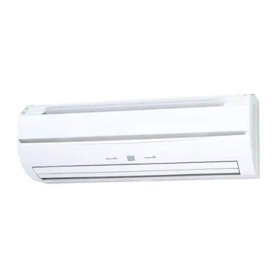
AirStage ASYA12GACH/ASHA12GACH Panduan Instalasi - Halaman 11
Jelajahi secara online atau unduh pdf Panduan Instalasi untuk Pendingin Udara AirStage ASYA12GACH/ASHA12GACH. AirStage ASYA12GACH/ASHA12GACH 15 halaman. Indoor unit

6.4.1. Button name and function
TIMER indicator lamp (Orange)
OPERATION indicator lamp (Green)
6.4.2. Checking the function settings
Press and hold the "MANUAL AUTO" button on the indoor unit for 3 seconds to check
the function settings. It is necessary to disconnect the power in order to return to normal
operation mode.
(1) Indoor unit and refrigerant address indication
Indication pattern
Indicator name
Indoor unit address
OPERATION indicator lamp
ON
(Green)
TIMER indicator lamp
Address: tens place (0.5s ON/0.5s OFF)
(Orange)
FILTER indicator lamp
Address: ones place (0.5s ON/0.5s OFF)
(Red)
• Indoor unit address example
(Example) ADDRESS : 24
OPERATION
ON
indicator lamp
(Green)
OFF
ON
TIMER
indicator lamp
0.5s 0.5s 0.5s 0.5s
(Orange)
OFF
ON
FILTER indi-
0.5s 0.5s 0.5s 0.5s 0.5s 0.5s 0.5s 0.5s
cator lamp
OFF
(Red)
• Refrigerant address example
(Example) ADDRESS : 30
OPERATION
ON
indicator lamp
1.0s
1.0s
1.0s
(Green)
OFF
TIMER
ON
indicator lamp
0.5s 0.5s 0.5s 0.5s 0.5s 0.5s
(Orange)
OFF
ON
FILTER indi-
cator lamp
OFF
(Red)
• Setting details
Function number
Item
01
Indoor unit address
02
Refrigeration address
For use with a remote controller, set all rotary switches to 0, and refer to "6.1. Setting the
address" for details.
All switches are set to 0 at the factory.
FILTER indicator lamp (Red)
Indication pattern
Refrigerant address
Flash
(1.0s ON/1.0s OFF)
1 cycle 12 sec
ON
10 sec
8 sec
1 cycle 12 sec
1.0s
1.0s
1.0s
1.0s
9 sec
OFF
Setting number
00 to 63
00 to 99
(2) Others
Indication pattern
Indicator Name
OPERATION indicator lamp (Green)
TIMER indicator lamp (Orange)
FILTER indicator lamp (Red)
(Example) Function : 31, Setting number : 2
OPERATION
ON
indicator lamp
0.5s
0.5s
0.5s
0.5s 0.5s 0.5s
(Green)
OFF
TIMER
ON
indicator lamp
0.5s 0.5s
(Orange)
OFF
ON
FILTER indica-
0.5s
0.5s
0.5s
0.5s
tor lamp
OFF
(Red)
6.5. Connecting the wired remote controller
(If necessary)
In order to connect the wired/simple remote controller to the external switch controller,
the wire assembly (Accessories) which is attached to the indoor unit needs be con-
nected to the end of remote controller cable.
(1) Use a tool to cut off the terminal on the end of the remote controller cable, and then
remove the insulation from the cut end of the cable.
For 2-wire type
20 mm
(2) Connect the remote controller cable with connecting cable with solder.
IMPORTANT: Be sure to insulate the connection between the cables.
For 2-wire type
Solder and insulate the connected parts.
Remote controller
cable (non polar)
Cut and insulate
For 3-wire type
Solder and insulate the connected parts.
Red
White
Remote controller
Black
cable
For dual control or group control
(3) Connect the cable of wired remote controller unit to the PCB of Control unit, and set
the DIP switch (SW1). Fasten the remote controller cable to the cable tie as shown
below.
When switching the DIP switch (SW1), be sure to turn off the power supply to the
indoor unit. Otherwise, the PC board of the indoor unit may be damaged.
For 2-wire type
Set the DIP switch (SW1)
2WIRE (Factory setting)
DIP switch
(SW1)
SW1
Connector
(CNC01)
Connecting cable
(Accessories)
Wired remote
controller cable
Indication pattern
Function number; tens place (0.5s ON/0.5s OFF)
Function number; ones place (0.5s ON/0.5s OFF)
Setting number: (0 to 9) (0.5s ON/0.5s OFF)
1 cycle 12 sec
9 sec
11 sec
10 sec
20 mm
For 3-wire type
Red
White
Black
Connecting cable
(Accessories)
Red
White
Black
Connecting cable
(Accessories)
CAUTION
For 3-wire type
3WIRE
Cable tie
(Accessories)
En-10
