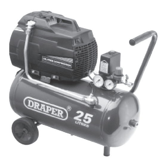
Draper DA6/201 Petunjuk Manual - Halaman 7
Jelajahi secara online atau unduh pdf Petunjuk Manual untuk Kompresor Udara Draper DA6/201. Draper DA6/201 12 halaman. Oil free compressors
Juga untuk Draper DA6/201: Petunjuk Manual (16 halaman)

Connect the compressor to the power supply.
Always turn on and off by the appropriate switch.
TURNING ON AND OFF (DA6/200/DA6/201,
DA25/180, DA25/200 - NOT DA200): THE ON/
OFF SWITCH.
(A) Fig.1. is located on the top of the pr essure
switch box.
These compressors are controlled by a pressure
switch assembly (B) Fig.2. which automatically
cuts off the power supply to the motor when
the upper limit is reached and restarts the
compressor automatically when the pressure
drops below the minimum.
TURNING ON AND OFF (DA200 ONLY):
This compressor is operated by a manual
on/off switch (F) Fig.4. and NOT by an
automatic pressure switch as fitted to the other
compressors shown in this booklet.
WARNING (DA6/200/DA6/201, DA25/180,
DA25/200):
The pressure switch is set at the f actory and the
compressor is also fitted with a saf ety valve in
the event of the pressure switch not functioning
correctly.
SETTING THE REQUIRED AIR PRESSURE:
DA25/180, DA25/200
Close the air outlet valve (C) Fig.2. and adjust
pressure by turning the knob on the pressure
regulator valve (D) Fig.2. clockwise to increase
pressure. Should it be necessar y to decrease
pressure open the the air outlet v alve (C) Fig.2.
slightly and then tur n the pressure regulator
valve knob (D) anticlockwise, re-close air outlet
valve (C).
DA200
This compressor is fitted with a pressure
regulator unit (G) Fig.4. so the pressure may be
regulated as necessary. To increase the pressure
turn the knob clockwise, to decrease the
pressure turn the knob anticlockwise.
DA6/200
Close the air outlet valve (K) Fig.3. and adjust
pressure by turning the knob on the pressure
regulator valve (L) Fig.3. clockwise to increase
pressure. Should it be necessar y to decrease
pressure open the the air outlet v alve (K) Fig.3.
slightly and then tur n the pressure regulator
valve knob anticlockwise, re-close air outlet
valve.
COMPRESSOR OPERATION
Fig.1.
Fig.2.
Fig.3.
(L)
Fig.4.
(F)
- 6 -
(A)
(B)
(D)
(C)
(K)
(G)
